ACES in 10 Minutes

ACES in 10 Minutes

May 17, 2014

Lately I’ve been taking a hard look at the Academy Color Encoding System aka ACES and trying to wrap my head around it. There are a handful of decent white papers on the topic but they tend to be overly technical. Through pulling tidbits from multiple sources, one can come to a decent understanding of the how’s and why’s of ACES but I was hoping to find some kind of an overview; something that presented the “need to knows” in a logical and concise way and wouldn’t require a big time commitment to understand. I did not find such a resource so I’m writing it myself.

Conceptually, I love ACES. In practice, I don’t have a terrible amount of hands-on experience with it. What I do know is from my own research and extensive testing in Resolve. It's quite brilliantly conceived but it seems to be catching on rather slowly despite established standards and practices and a good track record. Moving forward, I think as the production community meanders farther and farther from HDTV, ACES will emerge as the most appropriate workflow.

The principal developer of ACES is the Academy of Motion Picture Arts and Sciences (AMPAS).

“The Academy Color Encoding System is a set of components that facilitates a wide range of motion picture workflows while eliminating the ambiguity of today’s file formats.”

This description is vague but it seems to me that the Academy’s hope for ACES is to resolve two major problems.

1. To create a theoretically limitless container for seamless interchange of high resolution, high dynamic range, wide color gamut images regardless of source. ACES utilizes a file format that can encode the entire visible spectrum in 30 possible stops of dynamic range. Once transformed, all source material is described in this system in the exact same way.

2. To create a future-proof “Digital Source Master” format in which the archive is as good as the source. ACES utilizes a portable programming language specifically for color transforms called CTL (Color Transform Language). The idea is that any project mastered in ACES would never need to be re-mastered. As future distribution specifications emerge, a new color transform is written and applied to the ACES data to create the new deliverable.

The key to understanding ACES is to acknowledge the difference between “scene referred” and “display referred” images. 

A scene referred image is one whose light values are recorded as they existed at the camera focal plane before any kind of in-camera processing. These linear light values are directly proportional to the objective, physical light of the scene exposure. By extension, if an image is scene referred then the camera that captured it is little more than a photon measuring device. 

A display referred image is one defined by how it will be displayed. Rec.709 for example is a display referred color space meaning, the contrast range of Rec.709 images is mapped to the contrast range of the display device, a HD television.

Beyond this key difference, there are several other new terms and acronyms used in ACES. These are the “need to knows”. 

IDT: Input Device Transform:
Transforms source media into scene referred, linear light, ACES color space. Each camera type or imaging device requires its own IDT.

LMT, Look Modification Transform:
Once images are in ACES color space, the LMT provides a way to customize a starting point for color correction. The LMT doesn't change any image data whereas an actual grade works directly on the ACES pixels. An example of a LMT would be a "day for night" or "bleach bypass" look. 

RRT, Reference Rendering Transform:
Controlled by the ACES Committee and intended to be the universal standard for transforming ACES images from their scene referred values to high dynamic range output referred values. The RRT is where the images are rendered but it is not optimized for any one output format so requires an ODT to ensure it's correct for the specific output target.

ODT, Output Device Transform:
Maps the high dynamic range output of the RRT to display referred values for specific color spaces and display devices. Each target type requires its own ODT. In order to view ACES images on a broadcast monitor for example, they must first go through the RRT and then the Rec.709 ODT. 

The ACES RRT and ODT work together like a display or output LUT in a more conventional video workflow. For example when we use a Rec.709 3DLUT to monitor LogC images from an Arri Alexa. The combination of RRT and ODT is referred to as the ACES Viewing Transform. If you have ACES files, you will always need an ACES Viewing Transform to view them. An additional step to this would be to use an LMT to customize the ACES Viewing Transform for a unique look.

ACES Encoded OpenEXR:
Frame based file format used in ACES. It is scene referred, linear, RGB, 16 bit floating point (half precision) which allows 1024 steps per stop of exposure with up to 30 total stops dynamic range and a color gamut that exceeds human vision.

ACES Workflow utilizes a linear sequence of transforms to create a hybrid system that begins as scene referred and ends as display referred. It is a theoretically limitless space in which we work at lossless image quality (scene referred) but inevitably will need to squeeze into a smaller and more manageable space for viewing and/or delivery (display referred).

Any image that goes into ACES is first transformed to its scene referred, linear light values with an Input Device Transform or IDT. This IDT is specific to the camera that created the image and was written in ACES Color Transform Language by the manufacturer. This transform is extremely sophisticated and essentially deconstructs the source file, taking into account all the specifics of the capture medium, to return as close as possible to the original light of the scene exposure. Doing this allows multiple camera formats to be reduced to their basest, most universal state and allows access to every last bit of picture information available in the recording.

Big caveat - an ACES IDT requires viable picture information to do the transform so if it’s not there because of poor exposure then there's nothing that can be done to bring it back. Dynamic range cannot be extended and image quality lost through heavy compression cannot be restored. The old adage, “Garbage In, Garbage Out”, is just as true in ACES.

In ACES, scene referred images are represented as linear light which does not correspond to the way the human eye perceives light so are not practically viewable and must be transformed into some display referred format like Rec.709. This is done at the very end of the chain with the Output Device Transform, or ODT.

There are however a few more transforms that happen in-between the IDT and ODT, namely the LMT, Look Modification Transform, where grading and color correction happens and the RRT, Reference Rendering Transform, where the ACES scene referred values begin their transformation to a display / output format for viewing.

Because this process is very linear it should be fairly simple to explain in a diagram. Let’s try.

click to enlarge

I hope this overview is intuitive but in my desire to simplify, I easily could have overlooked important components. It's a very scientific topic and I'm coming at this from the practical viewpoint of a technician. I’m always open to feedback.

Anyone reading this who is interested in ACES I would encourage to join the ACES community forum at www.ACEScentral.com and read up on the latest developments and implementations of the project.

OFFICIAL ACES INFORMATION FROM THE ACADEMY OF MOTION PICTURE ARTS AND SCIENCES:

http://www.oscars.org/science-technology/sci-tech-projects/aces

http://www.oscars.org/science-technology/council/projects/pdf/ACESOverview.pdf

MORE RELATED ARTICLES:

http://www.finalcolor.com/acrobat/ACES_Nucoda%20r1_web.pdf

http://www.openexr.com/

http://www.poynton.com/w/ACES/

http://www.studiodaily.com/2011/02/is-justifieds-new-workflow-the-future-of-cinematography/

http://www.fxguide.com/featured/the-art-of-digital-color/

http://simon.tindemans.eu/essays/scenereferredworkflow

This article was updated 9/4/14 with input from Jim Houston, Academy co-chair of the ACES project. It was updated again on 4/2/17 with input from Steve Tobenkin from ACES Central

Luma and Waveforms

Luma and Waveforms

© 2009 NegativeSpaces (revised January, 2014)

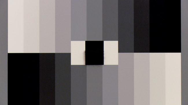
It’s late. I’m jetlagged, sleepless, and sitting in a hotel room. There's nothing on TV but I’ve got a Sony EX3, a Leaderscope, and a 11 step grayscale chart. Let’s talk about video luminance, or “Luma” as it’s more correctly known.

I'm sure there's a more elaborate definition out there but this one from Wikipedia sums it up nicely.

“Luma represents the brightness of an image (the “black and white” or achromatic portion of the image). Gamma-Compressed Luma is paired with Chroma to create a video image. Luma represents the achromatic image without any color, while the chroma components represent the color information. Converting R'G'B' sources (i.e. the output of a 3CCD camera) into luma and chroma allows for chroma subsampling, enabling video systems to optimize their performance for the human visual system. Since human vision is more sensitive to luminance detail ("black and white", see Rods vs. Cones) than color detail, video systems can optimize bandwidth for luminance over color."

Luma is measured on a waveform monitor by either a millivolt (mV) or IRE (%) scale. IRE is intuitive because it represents the percentage of light to dark and for HD Video that scale is from 0-109. 0% brightness, 0 IRE, is black. 100% brightness, 100 IRE, is white. 109 IRE is super white (basically some head room for your highlights). Makes sense to me.

Luma together with Chroma make up the HD video image and for engineering purposes both can be manipulated individually with the correct menu settings. Color is controlled by the camera's LINEAR MATRIX, COLOR CORRECTION, RGB GAIN (white balance), RGB PEDESTAL (black balance) settings whereas Luma/Brightness is controlled with GLOBAL GAIN, PEDESTAL, GAMMA, BLACK GAMMA, and KNEE. Some cameras have slightly different nomenclature or menu features but these are the basic and universal controls for manipulating video Luma. Use these Luma Control tools to affect the image's Tonal Response or how Shadow, Mid Tone, and Highlight information is rendered. 

In my opinion, creating beautiful HD images starts with good lighting. These engineering tools aren’t going to make a poorly exposed and poorly lit image good but they can help make a good image great. Remember that for an 8 bit camera you’re trying to cram all the scene’s brightness information into 256 levels of gray. That’s not much to work with and if you’re dealing with extreme contrast, the menu can help but there are limits to what's practical. 

The Variables:

MASTER PEDESTAL most noticeably affects the bottom of the waveform or the black/dark/shadow portion of the signal. If you think about your waveform as if it’s an actual pedestal or column you’ll see that by increasing or decreasing the Pedestal value, you’re actually lifting or lowering the entire signal. The picture portion of the video signal can’t go below 0 IRE so by lowering the Pedestal or “crushing the blacks” as it’s often referred to, what you’re actually doing is compressing the dark picture information down to pure black, 0 IRE. Some cameras have individual RGB Pedestal controls as well which can be used to affect chrominance in shadows. 

GAMMA as a television engineering topic is a complex one. But an interesting one! Gamma as it applies to camera menu settings primarily affects the Mid-Tones by starting at the middle of the waveform scale and either lifting or lowering the information there, which by default can subtly affect the shadows and highlights as well. In addition to a controllable Gamma level, most video cameras have several preset Gamma options such as HIGH, LOW, HD, SD, CINE, etc. Some but not all of these pre-made Gamma curves actually are a combination of various Knee, Pedestal, and Gamma settings designed to create a specific effect such as wide dynamic range, crushed blacks and popping whites, an overall lifted look, etc. At the end of this article, I’ll provide an example of this.

BLACK GAMMA is for Gamma fine-tuning and controls the area in-between middle gray and black, about 10-40 IRE. Black Gamma is a great way to punch up the blacks without crushing them or to lighten the fill side of a scene.

KNEE is electronic highlight protection and controls the top of the waveform or the bright/white/highlight portion of the signal. Video cameras have traditionally struggled with highlights and clipping so Knee circuitry was designed to help overcome this inherent problem. Where you set your knee point or in other words, where you tell the camera to begin compressing the white portion of the signal will greatly affect the quality of your highlights. Knee is not a power window in a color correction suite though. Knee needs some IRE to work with and if you’ve already exceeded the limits of the sensor’s bit bucket, adjusting the camera’s knee circuitry is going to have little effect. The Knee features in a camera's Paint menu often has a lot of controls other than just where the compression begins - you can also inject or remove detail as well hue and saturation into highlights, etc. 

GLOBAL GAIN is an important part of the equation but gain is an overall video level that either boosts or reduces the entire signal which affects both Chroma and Luma. It's important to draw the distinction between global gain and RGB gain which is how camera white balance is controlled. 

If you haven't seen them yet, please watch Andy Shipsides’ ENG Essentials on Abel Cinetech's Blog. His video on Gamma Matching is a great resource and is closely related to the information found in this tutorial. That video is more of a how-to on the subject whereas this is intended to illustrate how the camera menu settings specifically affect the grayscale and its accompanying waveform.

normal_chart.jpg

For the purposes of this test, I started by zeroing out all of the Picture Profile settings on the Sony, turned the knee off, and used the Gamma Mode of STD1 to set up a basic image to set up the comparison. The Leader's waveform mode was set to Composite instead of Parade (individual RGB waveforms) to better show the signal in terms of luma only. The lens iris was set to a F2.8/4 split and not adjusted for each of the various menu settings so as to illustrate how to affect the image in the camera instead of introducing or taking away light.

I want to see how the menu settings affect the entire picture from 0-109 IRE (note from 2014, should have been 0-100 IRE!)  so first I need to make white, white and black, black. Initially with my lens at a F2.8/4 split, white just hit 109 IRE but the true black (the black rectangle in between the two grayscales) needed some help so I brought my Master Pedestal setting down to -14, setting it at 0 IRE. With this combination of Iris and Pedestal settings, the middle of the scale crosses at around 60 IRE and we have picture information from 0-109 IRE.

Here is our basic waveform that has picture information from 0-109 IRE. This will be the basis of comparison for the other menu setups. 

1normalw.jpg

And the accompanying properly exposed Grayscale image:

1normal.jpg

What's most important to know when using these tools to affect the image's tonality, is how to identify shadows, midtones, and highlights on a waveform monitor.

1normalw_ident.jpg

Let's have a look at what happens when we start altering our shadows by setting the the Pedestal. If you’ve been following this blog, you’ll know my thoughts on the mistake of arbitrarily crushing black. Here’s why:

PEDESTAL -50

2ped-50.jpg
2ped-50w.jpg

As you can see, the information that would have been residing from 0-20 % has been crushed down to 0 IRE, or in other words, 0% picture information. No amount of post production wizardry is going to get that information back without introducing lots and lots of noise. So if you like crushed blacks, make sure you like them enough to live with them. Some shots can definitely benefit from stong, inky blacks but just be aware of what you’re doing.

Here’s what happens when we lift the Master Pedestal.

PEDESTAL +50

2pedp50.jpg
2pedp50w.jpg

As I mentioned, Pedestal will raise or lower the entire video signal. While lowering it is a way to introduce contrast, raising it will take it away. Because lowering it crushes dark picture information down to black, it may seem like raising it would crush bright picture information into white. That’s not the case. As the Pedestal is raised the signal is compressed and black gets lighter and white gets grayer. Some DP’s will shoot with the Ped always a little lifted just so they can hang on to as much shadow and highlight detail as possible. This is great if you know there's going to be a DI or some grading done later. If this isn’t the case, you’ve really got to get it right in the camera and the flat look of lifted pedestal isn't the most attractive.

With the Gamma setting, we have some control over our mid tones. These controls are pretty subtle but can be a great way to quickly punch up or reduce the contrast without touching the blacks. This is more of a personal preference but I routinely drop the gamma a little bit to get bolder, richer picture.

GAMMA +99

3gammap99.jpg
3gammap99w.jpg

GAMMA -99

4gamma-99.jpg
4gamma-99w.jpg

As I mentioned above, Black Gamma is a great tool for subtly fine-tuning the dark portion of the signal and can punch up the blacks without crushing them.

BLACK GAMMA +99

5bgammap99.jpg
5bgammap99w.jpg

BLACK GAMMA -99

6bgamma-99.jpg
6bgamma-99w.jpg

And now we can affect the top portion of the signal, or White, by altering our Knee Point. Knee is a little deceptive because what it does is tell the camera where in the signal to start clamping down the highlight information. For example by lowering the number to 80, you tell the camera to start compressing the picture information from 80 IRE on. It works within the limits of the sensor though and information that is very bright and exceeds its limits of won't be noticeably affected. By turning the Knee off, you are not doing anything electronically to protect your highlights. As I mentioned above, Knee needs some IRE to work with and if you’ve already exceeded the limits of the sensor’s bit bucket, adjusting the camera’s Knee circuitry is going to have little or no effect. Some cameras have a White Clip setting as well which will not record any part of the signal past the value you specify. The Sony EX1 does not have a White Clip setting.

Here is the KNEE set to 100 which starts the compression at 100 IRE. As you can see, the highlights start to roll off at that point on the scale.

7knee100.jpg
7knee100w.jpg

Here is the KNEE set to 75

8knee75.jpg
8knee75w.jpg

And the lowest value on the EX1, KNEE 50

9knee50.jpg
9knee50w.jpg

Highlight rendering can be further subtly fine tuned with the Knee Slope control which controls the shape of the Knee curve. This affects how quickly the highlights are rolled off to pure white. Very subtle!

KNEE 100, KNEE SLOPE +99

10knee100sp99.jpg
10knee100sp99w.jpg

KNEE 100, KNEE SLOPE -99

11knee100s-99.jpg
11knee100s-99w.jpg

CAMERA MATCHING:

We can use these tools to match the gamma curves of different cameras to one another. Also, your camera's pre-made Gamma options - STD, CINE, etc - are really a combination of various Luma control settings. With skillful use of these tools, you can actually recreate any of these effects pretty closely or even design your own custom gamma curve.

In this example, I set the camera to CINE 2, the most aggressive of the pre-made gamma options on the EX1. I left the lens to a F2.8/4 and captured the waveform. You'll notice because this curve clamps the signal down so much, it's quite a bit darker than STD1.

Here it is:

match1.jpg
match1w.jpg

Next I zeroed out the settings out and reset the camera to Gamma STD1. Because CINE2 uses such aggressive compression, I had to close down half a stop on STD 1 to bring it within range. Using the menu, I adjusted the following settings to arrive at a fairly close match to CINE2, not perfect but pretty close.

PEDESTAL -11

BLACK GAMMA +12

KNEE 59

KNEE SLOPE -37

GAMMA -99

Here are the two curves superimposed over one another. Pretty close. With a little play in the iris, these pictures would be fairly well matched.

match_comp.jpg

And for kicks, to better illustrate how aggressive these pre-made gamma curves can be, here are the Cine curves from the Sony XDCAM-EX camcorder series (Iris is the same for each curve):

Cine 1

cine1_comp.jpg

Cine 2

cine2_comp.jpg

Cine 3

cine3_comp.jpg

Cine 4

cine4_comp.jpg

Please support this blog by leaving comments and feedback. It's only through user support and feedback that this content can be fine tuned so I always appreciate hearing from you. 

Painting HD Cameras - Skin Tones

Painting HD Cameras - Skin Tones

© 2009 NegativeSpaces (revised January, 2014)

In my experience color correcting video cameras in the field, 9 times out of 10 I’m trying to resolve some sort of skin tone issue – taking green out, bringing overly magenta skin back within a normal range, or sometimes just injecting a little bit of warmth and saturation. Knowing how to correctly use a video camera’s User Matrix menu and Color Correction menu as well as the Tonal Control menu is the key to working through these inevitable problems. In building upon my previous article on in-camera color correction for HDTV, this next article will specifically address how to use the various matrix menu attributes to affect skin tones.

This article builds off what was established in Painting HD Cameras - Basic Colorimetry. 

Technical Notes:

The images used in this article were created with a Panasonic HDX900 and the stills and vectorscope information were captured from a Leader LV 5330 Multi-SDI Monitor. Because a Panasonic camera was used, the workflow presented and menu features explained are those found on Panasonic cameras. The feature set on Sony cameras is similar enough though that I feel that if you know one system, you should be able to apply the same concepts to the other. The chip chart used was a DSC Labs CamBelles Chart. These charts are the standard for video engineering and camera alignment. Because the colors and values are so uniformly printed and tested, they can be measured electronically with repeatable results. Correct use of DSC Labs equipment can not only be used to calibrate and match equipment but to paint custom looks in the controlled environment of your studio.

On naming conventions: 

In most Panasonic cameras, the Linear Matrix is referred to as User Matrix and the Multi Matrix is referred to as Color Correction. In Sony cameras, Linear Matrix is referred to as Matrix Linear and the Multi Matrix is referred to Matrix (Multi). As this is a Panasonic oriented article, from here on out I'll be using the Panasonic nomenclature. 

Part 1: Overview

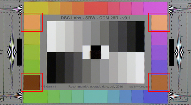
First to re-hash, there are six attributes that affect a video camera’s Linear Matrix: B-G, B-R, G-B, G-R, R-B, R-G. Those are read “Blue into Green, Blue into Red, etc.” Additionally, there are twelve Color Correction attributes we can modify: R, Mg, B, Cy, G, Yl, Yl-R, R-Mg, Mg-B, B-Cy, Cy-G, and G-Yl. For an in depth account of how these attributes work by pushing and pulling colors around the vectorscope, please refer to the previous tutorial. Using the handy DSC Labs Chroma Du Monde Chart with its 4 "generic skin tone" swatches, let's have a look at our camera's "out of the box", default colorimetry:

normal_chart_w_skintones.jpg
normal_vector_skin.jpg

Interestingly enough, virtually all human skin regardless of its hue or saturation resides somewhere within or nearby this red circle which for simplicity we'll call the "Skin Tone Region". The area resides along the I line on the Vectorscope and above the Q Line (see the intersecting lines on the graphic below). Where the Q Line crosses the I Line, skin tone saturation is at zero. The closer the skin tone information is to the boundary of the circle, the greater its saturation. Smart camera software such as Skin Tone Detail Circuitry knows to look within the Skin Tone Region and is thus able to isolate the information there to make independent adjustments. This is very helpful because it becomes easier to predict how the values are going to move around on the vectorscope as adjustments are made to the camera.

IQ-AXIS.jpg
skintone_region2.jpg

Now before we start playing, let's get a better idea of how these variables will affect actual human skin by using the DSC Labs CamBelles chart. Obviously sitting models would be better but for what it is, this chart is incredibly precise and I've used it to paint looks in the studio that have worked perfectly well in the field. 

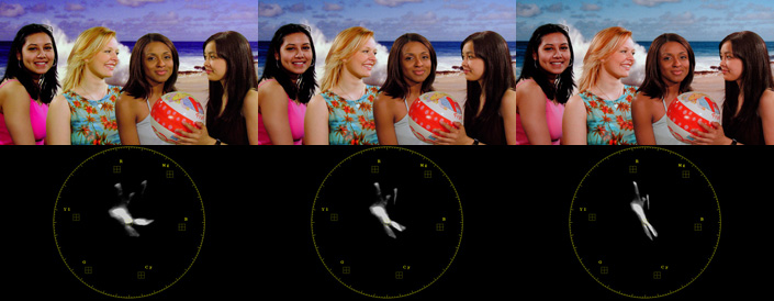
The lovely ladies of DSC:

1normal.jpg

There is a good variety of skin tones here and the light in the scene is modeled enough that you can examine a good range of values. Also the fact that they're wearing bright clothes and are on a blue background helps to isolate the skin tones on the vectorscope.

Here's what they look like on the Vectorscope:

isolated_skintone.jpg

This isn't a tutorial on tonality but part of getting good colors means getting a good exposure. This is what my properly exposed and properly white balanced CamBelles look like on the waveform. 

1normalwfm.jpg

And if you have False Color on your monitor, you can use it to confirm your exposure:

1normalfc.jpg

Usually you want to keep it in the green-yellow zone for light skin tones and green-blue for dark. Orange is 80% which is where skin starts to break up so you definitely don't want your key light hitting that hard.

Skin tones can also be affected globally with Master Saturation Controls. Increased Saturation on the left and decreased Saturation on the right:

sat_comp.jpg

Part 2: User Matrix menu and skin tones

Typically you wouldn't use matrix adjustment to specifically affect skin tones as these are more global adjustments but it's good to see what the effect is. You're also hardly ever going to only use one of these adjustments. When creating a custom look, you'll most likely be pushing values around in all six menu options.

For example, let’s look at a side by side of the Cambelles when you put the G-B (Green into Blue) attribute at its maximum value, +63 on the left and its minimum value, -63 on the right:

b-r_example.jpg

As you can see, you’re never only affecting the skin tones. In your quest to render the perfect skin you’re also affecting plenty of other colors. It’s very easy to get caught in an endless cycle of color correction where you fix one thing only to create a new problem with another color. Only through trial and error and understanding the basic principles behind how in-camera color correction works will you be able to quickly execute the best solution.

Now let's have a look at both what happens to our skin tones when we adjust each of the user matrix variables:

B-G, BLUE INTO GREEN: 

On the left - Positive Value, In the middle - Default Value, On the right - Negative Value

blue-green.jpg

B-G +63 (increase in value)

B-G –63 (decrease in value)

b-g-63.jpg

B-R, BLUE INTO RED: 

On the left - Positive Value, In the middle - Default Value, On the right - Negative Value

blue-red.jpg

B-R +63 (increase in value)

b-rp63.jpg

B-R–63 (decrease in value)

b-r-63.jpg

G-B, GREEN INTO BLUE: 

On the left - Positive Value, In the middle - Default Value, On the right - Negative Value

green-blue.jpg

G-B +63 (increase in value)

g-bp63.jpg

G-B –63 (decrease in value)

g-b-63.jpg

G-R, GREEN INTO RED: 

On the left - Positive Value, In the middle - Default Value, On the right - Negative Value

green-red.jpg


G-R +63 (increase in value)

g-rp63.jpg

G-R –63 (decrease in value)

g-r-63.jpg

R-B, RED INTO BLUE: 

On the left - Positive Value, In the middle - Default Value, On the right - Negative Value

red-blue.jpg

R-B +63 (increase in value)

r-bp63.jpg

R-B –63 (decrease in value)

r-b-63.jpg

R-G, RED INTO GREEN: 

On the left - Positive Value, In the middle - Default Value, On the right - Negative Value

red-green.jpg

R-G +63 (increase in value)

r-gp63.jpg

R-G –63 (decrease in value)

r-g-63.jpg

Part 3: Color Correction menu and skin tones

Unfortunately I don't have CamBelles examples for working with the Color Correction menus. The attributes you'll be working with the most in regards to skin tones are the following three video colors: Red-Yellow (Yl-R), Red (R), and Yellow (Yl).

In the Color Correction menu set, we can isolate and modify the following twelve individual vectors: six primary video colors - Red (R), Yellow (Yl), Green (G), Cyan (Cy), Blue (B), and Magenta (Mg) and the six colors in between the primaries - Red-Magenta (R-Mg), Magenta-Blue (Mg-B), Blue-Cyan (B-Cy), Cyan-Green (Cy-G), Green-Yellow (G-Yl), and Yellow-Red (Yl-R). 

vectorscope2.jpg

As exemplified in the above graphic, the colors in and around these areas will be affected by their corresponding adjustments. To modify the Hue or Saturation of Red, use the "R" Color Correction attribute, for the colors in-between Yellow and Red, use "Yl-R", etc. 

yl-r.jpg

These Color Correction attributes are modified with a Phase and Saturation control. A negative Phase value (-) will move the color to the left on the vectorscope, a positive Phase value (+) will move it to the right. A negative (-) Saturation value will move the color closer to the center of the vectorscope, decreasing saturation and a positive (+) value will move it closer to the edge of the circle, increasing saturation. By altering the Phase on an individual color you are moving it out of alignment with other colors and reducing the amount of shades the camera can reproduce. Using these controls you can work on individual colors (such as skin tones) and subtly alter their hue and saturation but you still will affect any other color that contains the color you are modifying. The effect is far more subtle than the Linear Matrix adjustments, however is often necessary to arrive at a very specific hue or color saturation. Color correction in post production allows for a much finer degree of control so in some cases, it's best left to them. 

phase_sat.jpg

As mentioned in the previous article, you're very rarely only going to work with one attribute at a time. It's really understanding how they're all used together that's the key to good camera painting. Every task is different and there is no "one size fits all" approach. However I will Yl-R in Color Correction is often where I start when trying to inject some warmth and life into dull looking skin. Please support this blog by leaving comments and feedback. It's really only through user support and feedback that content can be fine tuned so I always appreciate hearing from you.