Syncing Audio in Resolve 9 Lite

Syncing Audio in Resolve 9 Lite

Happy Sunday. It's a beautiful one here in NY so can't wait to get on the bike. That said, this will be quick.

Whenever I spend an aggravating amount of time trying to figure something out, I feel that it's a worthy topic for a blog post. I've been checking out the Resolve 9 Lite Beta and couldn't figure out for the the life of me how to sync audio. Couldn't find any decent tutorials or workflow guides online or on the BMD forums. After enough "right clicking" I finally found it. 

From the top -

1 Download Resolve 9 Lite >>>

2 Create your project and set it up according to your camera media specs.

3 In MEDIA, load your camera files along with the corresponding sound files. It helps to make a bin for both in the Media Pool window, like "Picture" and "Sound".

media1.jpg
media_pool.jpg

4 In CONFORM, create a new Timeline and call it something like SYNCED or you can use the Camera Roll Number. Whatever works for you really. 

conform1.jpg

Now select the Bins for Audio and Video in the Media Pool and RIGHT CLICK on the Timeline you just created. Select "Link With Audio From Selected Bins". A prompt will come up confirming your selections. Click OK. 

conform2.jpg

5 You can confirm that you now have sync sound on your video clips by scrubbing through the timeline.

sound1.jpg
sound2.jpg

For now there is no way to sync audio without synchronous timecode and no way to slip in the event of drift. That's a problem but one that I'm sure will be addressed. Another problem is that this only works with truly MOS video clips. If there are audio channels in the ProRes Files (or whatever), even if they don't actually contain any sound, Resolve will not overwrite these channels with new ones.

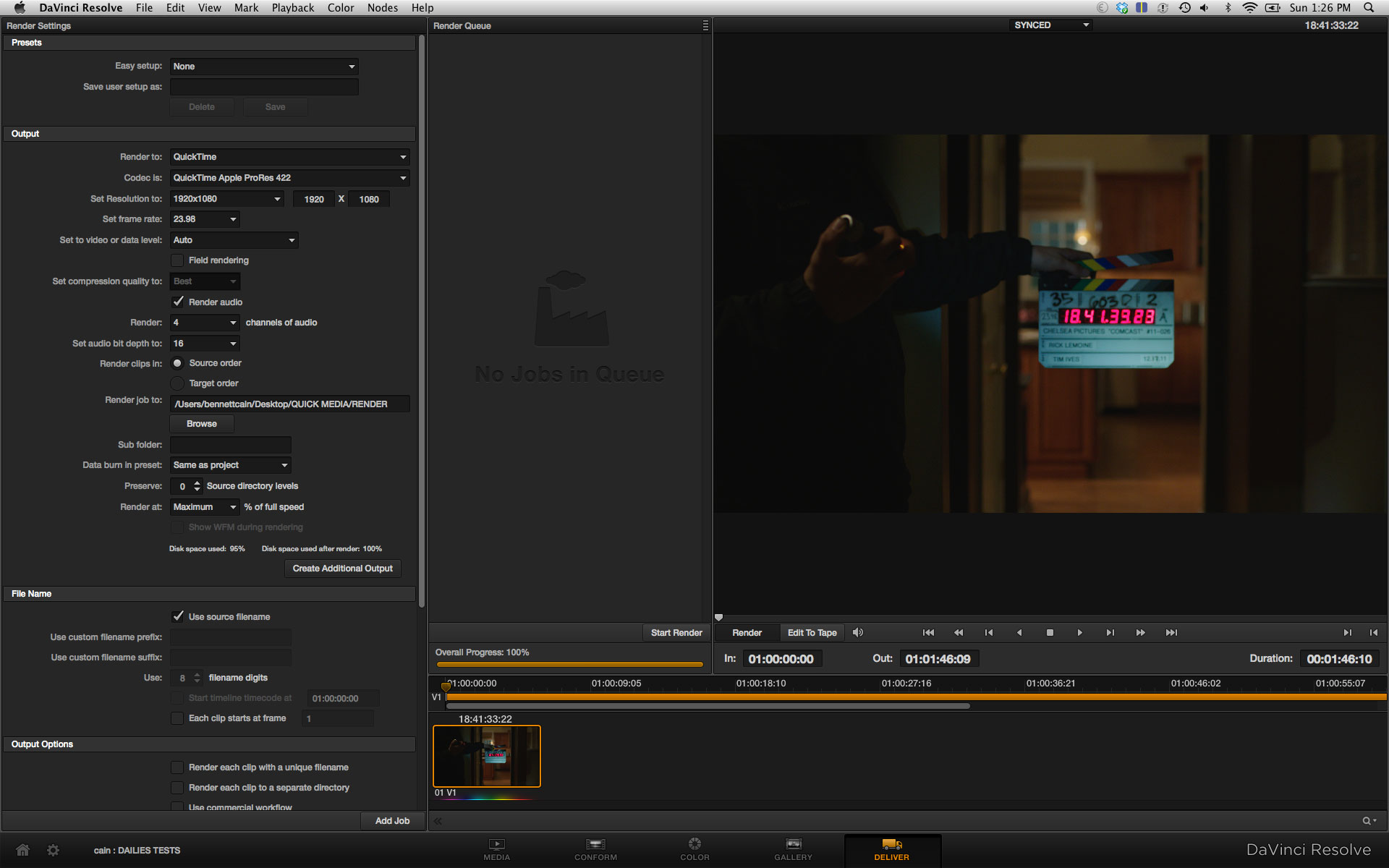
6 In DELIVER, make sure to select "Render Audio" in Output and select however many channels.

render_screen.jpg
render_audio.jpg

There you have it - Color Corrected, Sync Sound Dailies. For free software, this is a pretty powerful solution for HD deliverables. I'm not going to get into a bunch of software comparisons / pros and cons right this moment but I do think with Lite you get an awful lot of BANG for your "No Buck". Hard to argue with that. 

Arri Alexa - Legal vs. Extended

Arri Alexa - Legal vs. Extended

August 1, 2012

While this article is very specfic to the Arri Alexa and its digital color workflow, in a broader sense much of the information here can be readily applied to the difference between YCbCr 422 digital video, RGB Data, and all the things that go wrong when we monitor in video but post process RGB Data.

That said, here we go.. 

Anyone doing on-set color correction for the Alexa is well acquainted with the LogC to Video LUT workflow. I'm guessing many of the readers of this blog are already savvy but just in case, here's a refresher -

First a definition - "Log C" is a video recording option on the Alexa and stands for "Log Cineon". This encoding scheme is based on the Kodak Cineon Curve and it's purpose is to preserve as much picture information as the sensor is able to output.

Here's Kodak's Cineon (Log) encoded LAD test image (screengrab from LUT Translator software) -

cineon_log.jpg

Log encoding is most evident in the form of additional latitude in the shadows and highlights that would be lost with a traditional, linear video recording. A log encoded recording results in images that are very low contrast and low saturation, similar in quality to motion picture color negative scanned in telecine as this is what Cineon was designed to do. This unappealling Log image will inevitably be linearized using a Lookup Table (LUT) into something with a more normal or, "video", level of contrast and saturation.

Kodak Cineon LAD image, now linearized with a 3D LUT:

cineon_linear.jpg

All LUT's take input values and transform this data into an output. In the case of Arri Alexa LUT's we input Log C and output Rec.709 Video. In this workflow, the terms "Video" and "Rec.709" are used interchangeably. Rec. 709 is the color space for HDTV and all the color correction we're doing in this workflow is within this gamut.

Rec.709 Gamut

Lookup Tables come in 2 flavors - 1D or 3D. 

From Autodesk glossary of terms:

1D LUT:A 1D Look-up Table (LUT) is generated from one measure of gamma (white, gray, and black) or a series of measures for each color channel. With a pair of 1D LUTs, the first converts logarithmic data to linear data, and the second converts the linear data back to logarithmic data to print to film.

3D LUT:A type of LUT for converting from one color space to another. It applies a transformation to each value of a color cube in RGB space. 3D LUTs use a more sophisticated method of mapping color values from different color spaces. A 3D LUT provides a way to represent arbitrary color space transformations, as opposed to the 1D LUT where a component of the output color is determined only from the corresponding component of the input color. In essence, the 3D LUT allows cross-talk, i.e. a component of the output color is computed from all components of the input color providing the 3D LUT tool with more power and flexibility than the 1D LUT tool. See also 1D LUT.

LUT's are visualized by "cubes". Consequently, 3D LUT's are often referred to as cubes as well.

Here's a cube representing a pre-LUT image (from Pomfort LiveGrade):

log_cube.jpg

And the same image, linearized by a 3D LUT:

linear_cube.jpg

And an example recorded with the Alexa camera: the Chroma du Monde in LogC ProRes 4444 to SxS. 

cdm-log2.jpg

And the same image, its color and tonality transformed into more normal looking HD video, with a Rec.709 3D LUT from the Arri LUT Generator

cdm-linear2.jpg

Summary of a possible LogC to Video on-set workflow:

1. We feed a Log C encoded YCbCr (422) HD-SDI video signal out of the camera's REC OUT port into...

2. our HDLink Pro, Truelight Box, DP Lights, Pluto, or whatever color management hardware we happen to be using. 

3. We then load the hardware interface software - LinkColor or LiveGrade for the HDLink Pro or the proprietary software for our other color management hardwares. 

4. Using our software, we do a real-time (that is, while we're shooting) color correct of the incoming Log encoded video signal. Through the use of 3D LUT's we non-destructively, i.e. the camera's recording is totally unaffected, linearize the flat, desaturated Log image into a more normal looking range of contrast and color saturation. On-set color correction, herein referred to as "Camera Painting" for the purposes of this article, has the option of being applied either pre or post linearization that is before or after the 3D LUT aka, "DeLog LUT" is applied.

This selection is known as Order of Operations and it's very important to establish this when working with a facility such as Technicolor/Post Works or Company 3/Deluxe to generate the color corrected production dailies. In the two most widely used on-set workflow softwares, LinkColor and LiveGrade, the user can specify this Order of Operations.

Painting Pre-Linearization in LiveGrade:

prelinear.jpg

And painting Post-Linearization in LiveGrade

postlinear.jpg

Toggling between pre and post painting in LinkColor:

lctoggle.jpg

I'll get more into the differences between working pre or post but for now, simply take note that it's an important component of any on-set color color correction workflow, the ultimate goal of which is to close the gap between the work done on set and in post. 

5. After linearzing and painting the Log encoded video signal, we display the pleasing results on our calibrated Reference Grade Monitor (the most important component of working on-set) for evaluation and approval by the Director of Photography. We can also feed this color corrected video signal to video village, client monitors around the set, the VTR Operator or whomever else requires it. 

6. Additionally, the color correction data we create through this process can be output in the form of 3D LUT's and/or Color Decision Lists (ASC-CDL) to be applied to the camera media in software such as Scratch Lab (which I use and recommend), Resolve, Colorfront OnSet Dailies, YoYotta Yo Dailies, to create color corrected production dailies - files smaller in size than the camera master to be used for review, editorial, approvals, or any number of other purposes.

This final step I've outlined will be the focus of the article you're reading - how do we create color correction data on the set that will "line up" with our camera media in post production software to create dailies files that look the way they're supposed to look. 

Anyone who has done this work has encountered bumps and occassionally chasms in the road along the way. All parties - DIT's, DP's, producers, dailies colorists, and post production facilities are becoming more experienced with the workflow so the process is getting easier.

What I've found to be at the root of the problems you'll likely encounter though is a matter of nomenclature and the confusion that comes from the exact same terms essentially having different meanings in video production, that is YCbCr 422 digital video, and post production where we deal with RGB Data. Fortunately once a few points are acknowledged, this hazy topic comes into sharp focus. 

At the very beginning of the workflow we have three options for the Log C video output level on the camera's REC OUT channel - Legal, Extended, and Raw. For the purposes of this article, only Legal and Extended are of concern (image from Alexa Simulator). 

alexaout.jpg

Our recording, be it ProRes 4444 to the camera's on-board SxS cards or ArriRaw to an external Codex, OB1, or Gemini, will be Log C encoded so the monitor path we're going to paint will also be Log C. This workflow is recording agnostic in that it's not specific to ProRes, ArriRaw, or Uncompressed HD though you may use the camera's outputs differently depending on the recording. 

In the on-set camera painting ecosystem we have the following variables -

1. REC OUT camera output levels: Legal or Extended

2. Arri Log to Video Linearization 3D LUT choice: Legal to Legal, Legal to Extended, Extended to Legal, or Extended to Extended. Note: while you certainly can use any LUT of your choice as your starting point, even one you custom created, these Arri LUT's are universally used in Alexa post production and in most dailies software so by using them on-set, you're one step closer to closing the gap. An exception to this might be starting your painting with a specific film emulation LUT as specified by the post production facility. 

3. Software Scaling: In softwares such as LinkColor and LiveGrade we're able to scale our incoming and outgoing video signals to either Legal or Extended levels on top of any scaling we're doing with 3D LUT choice and/or camera output levels. 

The combination of these 3 variables and their choice between Legal orExtended, all of which will either expand or contract the waveform, will result in wildy different degress of contrast. Understanding scaling and acknowledging that is inevitable when transitioning between video and data is the key to creating a successful set to post digital color workflow. The ultimate goal of which is to create color correction data that when applied to camera media, will result in output files with color and contrast that match as closely as possible the painting done on-set. If this work done under the supervision of the director of photography results in dailies files that look nothing like what was approved, then there's little point in working like this in the first place.

So, what's the best way to get there? 

The short answer is that if it looks right it is right. Whatever workflow you come up with, if your on-set color correction lines up with your output files then you win. There is a specific workflow that will consistently yield satisfactory results but because of existing nomenclature, aspects of it seem counterintuitive. 

At the very root of this problem is the fact that on the set we monitor and color correct in YCbCr 422 Digital Video but we record RGB (444) Data. This RGB recording will inevitably be processed by some sort of post production software - Resolve, Lustre, Scratch, etc - that will interpret it as RGB Data and NOT YCbCr Video.

Our workflow is a hybrid - one including a video portion and a data portion. As soon as we hit record on the camera, we're done with the video portion and are now into post production dealing with data where the terms "Legal" and "Extended" mean very different things than they did on-set. 

In the video signal portion of our workflow, that is the work we do the set, we monitor and evaluate the YCbCr video coming out of the camera using the IRE scale where "Legal Levels" are 0-100 IRE, herein referred to as 0-100% for the purposes of this article.

The picture information represented by this RGB Parade Waveform is a Legal Levels, 0-100% HD video signal.

rgb_parade_legal.jpg

Above and below Legal Levels is the Extended Range of -9-109%. In the case of the Alexa, Extended level video output will push pixel values into this "illegal" area of the video waveform. 

That said, in terms of YCbCr Video, the difference between Legal and Extended is that an Extended Levles signal will have picture information from -9-109% whereas with Legal Levels, signal will be clipped at 0% and 100%

But because we are dealing with YCbCr which is a digital video signal, another system can be employed for measurement, the one used to describe all RGB Data images in post production -

Code Values.

On paper, 1024 levels are used to describe a 10 bit digital image represented with the code values 0-1023. For 8 bit digital images, it's 0-255. In practice, only values 4-1019 are used for image information, 0-3 and 1020-1023 being reserved for sync information. In the case of Alexa and for the sake of simplicity, we'll assume that we're working in the 10 bit 0-1023 range even though only values 4-1019 are used. Another point for the sake of simplicity, 0-1023 will be used in place of 4-1019 to denote Extended Range levels.

DaVinci Resolve, like all post production image processing software, processes RGB data and not YCbCr video so employs the code value system of measurement. Note the waveforms in Resolve do not measure video levels from 0-100% but instead 10 bit code values from 0-1023.

resolve_full_wfm.jpg

An image that can use all values from 4-1019 is described in a post production system as a "Full Range" image. Unfortunately, another term used interchangeably for Full Range is "Extended Range". They are the exact same thing. In our hybrid workflow utilizing both video and data, this little bit of nomenclature opens the floodgates to confusion. This is the first component of our problem. 

And this is the solution -

Because of inevtiable scaling between Video Levels and Data Levels, for all intents and purposes; in post production, "Legal" Video Levels 0-100% = "Extended" Range 0-1023 RGB Data. 

Unless otherwise specified in software, RGB Data Levels 0-1023 will always be output as 0-100% Video Levels.

Extended Range Data = Legal Range Video

Here's a teapot. This image was recorded on Alexa in Log C ProRes 4444. I created a color correct on the set expanding the Log encoded image to 0-100% video level using LiveGrade software. I recorded the resulting image to a new video file using Blackmagic Media Express. I then took this file into Resolve and Final Cut Pro 7 for measurement. 

teapot.jpg

On the left is the teapot's waveform in Resolve. On the right is the teapot in Final Cut Pro which measures in the same IRE (%) video levels you used on the set.

Resolve-FCP.jpg

As you can see, the image produces the exact same waveform but is measured two different ways. On the left, an "Extended" Range 0-1023 RGB Data image and on the right, a "Legal" Levels 0-100% Video image. They are the same. 

This miscommunication is only compounded by the fact that the very same code values used by post production image processing software to measure RGB Data can also be used to measure live digital video signals such as YCbCr. In this system of measurement, Legal video levels of 0-100% are represented by the code values 64-940 and Extended video levels of -9-109% use the code values 4-1019. This difference in measurement which can be used to describe the exact same image as both video and data is the second component of our problem. 

Here's the teapot again.

legal_LUT_resolve.jpg

This time I used a Legal Output Levels 3D LUT to process in Resolve. Have a look at the waveform.

legal_wfm_Resolve.jpg

By applying a Legal Levels LUT to an RGB image, we have clipped our blacks at the Legal for Digital Video code value of 64 and our whites at the Legal for Digital Video code value of 940. 

We've established that post production image processing software like Resolve only works with Full Range (aka Extended Range) RGB Data so interprets everything that comes in as such. This Legal Levels LUT describes an absolute black code value of 64. All Resolve knows is to apply the instructions in the LUT to whatever 10 bit image it's currently processing so it puts the darkest value in our image at 64. 

Because of scaling in post production, 0-1023 in RGB Data code values equals 0-100% video levels; the code value of 64 does equal 0% video level and the code value of 940 does equal 100%. However a Legal Levels LUT can result in double legalization of the video signal where you will have "milky" blacks and "grayish" whites that cannot be pushed into 0-100% video levels. This is the third component of our problem. 

And here's the resulting waveform using the Legal Levels 3D LUT as output by Resolve and then measured in Video Levels with Final Cut Pro. Please note that when you send YCbCr video out of FCP via a Kona card, DeckLink, or something similar to a an external hardware scope, the waveform there is identical to the scopes in the software.  

legal_clip_fcp.jpg

What we've done by processing the image with this Legal Levels LUT is force our entire range of picture information into 64-940 which results in video levels of about 5.5-94%. All picture information that existed above or below this is crunched into these new boundaries. If you attempt any additional grading with this LUT actively applied you won't be able to exceed 5.5-94%. This is a very commonly encountered problem when working with a facility where additional color correction will be done. Just as video levels constrained 5.5-94% are of little use to you on-set, they're of even less use to a dailies colorist so will be discarded.

Because image processing software is always Full Range (aka Extended Range) the default Log C to Video Lookup table used by both Resolve and Scratch for use with Alexa media is this LUT "AlexaV3_K1S1_LogC2Video_Rec709_EE" which is available for download from the Arri LUT Generator.

arri_lut_gen.jpg

Let's dissect this label. 

AlexaV3_K1S1_LogC2Video_Rec709_EE

AlexaV3: Alexa Firmware Version 3

K1S1: Knee 1, Shoulder 1. This is the standard amount of contrast for this LUT and is identical to the Rec709 LUT applied by default to the camera's MON Out port. Contrast can be softened by choosing K2S2 or even more so with K3S3. The knee being shadows and the shoulder being the highlights, custom contrast can be defined with various combinations of this. 

LogC2Video: We're transforming LogC to Video

Rec709: In Rec709 color space

EE: LUT's transform a specified input to a specified output. "EE" reads Extended IN and Extended OUT.

This last bit. "EE", is of the most concern to us. In this context, EE, Extended to Extended, or Extended values input, Extended values output. If this were a EL LUT, or Extended to Legal, it would scale the Full Range Data 0-1023 to the Legal code values of 64-940 which as illustrated above, presents a significant problem. 

I would make the case that instead of labeling this LUT "Extended to Extended", a more logical title would be "Full Range to Full Range" as what this LUT assumes is you have 0-1023 possible code values coming in and 0-0123 possible code values going out which is always the case. Because this is how all image processing works in post production software, it's the only real way of transforming a color space on the set that makes any sense to post. This is the fourth component of our problem. 

Here is the LogC encoded ProRes 4444 recording of the tea pot captured to SxS card.

teapot_legal.jpg

Here's the waveform of this video file opened in Resolve on the left, measuring RGB Data values, and Final Cut Pro on the right, measuring 0-100% Video Levels. 

log_fcp_resolve.jpg

Note there are slight differences in the way these two softwares perform their trace but for all intents and purposes, they are the same. 

Here is the same image of the teapot, recorded externally from the Legal Levels Log C encoded YCbCr video on the camera's REC Out port via Blackmagic Media Express. This is a clean image and was not passed through any software or color correction processing before it was recorded. 

teapot_legal_log.jpg

Here is the waveform of the external recording from the Legal Levels Log C YCbCr video output compared to the waveform of the same image but recorded to Log C ProRes 4444 on the camera.

camera_external_compare.jpg

They're the same.

Alexa's Legal Level Log C video output = the wavefrom of the Log C ProRes 4444 recording. 

This is very important to acknowledge as any camera painting we do on the set needs to correspond to our recording. If it doesn't, the color correction data we generate through this process will result in output files that don't look anything like what was intended.

Here's the teapot again recorded externally from the camera's LogC encoded REC output but this time in Extended Output Levels. 

teapot_extended.jpg

Here they are side by side for comparison - Log C Legal Levels on the left and Log C Extended Levels on the right (images captured via external recording)

teapot_legal_extended_sidebyside.jpg

And here's a comparison of the waveforms, on the left Log C Legal, on the right Log C Extended.

log_wfm_differences.jpg

The actual pixel content of this Extended Range waveform is the same as the Legal, merely scaled in a mathematically pre-determined way to fill the "Extended" video range of -9-109. However as we've established, this extended range video signal doesn't necessarily correspond to the RGB Data we're recording. 

Another point we've established is that only Log C Legal Output Levels from the camera match the Log C ProRes 4444 recording. The waveforms are identical. As is evident in the waveform differences between Legal and Extended video output, if we attempt camera painting with an Extended Range signal and it isn't re-scaled to Legal Video Level in either our color correction software/hardware or with a LUT, the resulting color correction data will be applied to a different waveform than is being recorded so will not line up correctly with camera media.

This is where the workflow outline gets software specific. I performed these tests using LiveGrade which is what I'm using on my current show, season 2 of Girls for HBO. While much of what's outlined here can be readily applied to LinkColor and other softwares, there are processing differences between these that will yield potentially different results.

It's been theorized that some of the problems experienced with on-set color correction workflows originate with the HDLink Pro box itself as processing inconsistencies have been documented. It's always been interesting to me that Blackmagic Design would produce a product like this and then leave it 3rd parties to implement its functionality. Because of this, advantages in working with higher end on-set solutions such as Truelight are apparent but the HDLink Pro and 3rd party software is an exponentially cheaper investment. 

Pomfort recently published a Workflow Guide for LiveGrade that explains some of what I've outlined here. This article and my own were developed in tandem so can hopefully be used as such to come to a more complete understanding of how this workflow operates on a technical level. 

I'm going to lift and slightly re-order some of the copy from Pomfort's article to illustrate my final point.

LiveGrade Workflow:

From Pomfort: 

Processing chain in LiveGrade

3D LUTs are applied on RGB images. In post production systems, RGB images are usually using all the code vaues available – so for example a 10-bit RGB image uses code values 0 to 1023. This means that lookup tables made for post production systems expect that code values 0 to 1023 should be transformed with that LUT.

To be able to compute color manipulations in a defined code value range, LiveGrade converts incoming signals so that code values 0 to 1023 are used (see Figure 1). So the processing chain of LiveGrade simulates a post-producation pipeline for color processing. This means that LiveGrade’s CDL mode always will expect regular, “extended-range” lookup tables (3D LUTs).

From the conclusions I've come to, Pomfort is correct in that the only way for camera painting done on-set to be truly useful in post production is by simulating their pipeline. The first component of this successful workflow is using the same Lookup Tables on the set that will be used in post which are the Extended Range or "EE" 3D LUT's.

That is, 0-1023 code values going in and 0-1023 code values going out.

When using LiveGrade in "Alexa" Mode where we cannot load a 3D LUT of our own choice, the LUT used here is the "AlexaV3_K1S1_LogC2Video_Rec709_EE". Additionally, this is the exact same LUT found in Resolve when you apply "Arri Alexa Log C to Rec709". In Scratch Lab, when you load an Alexa Grading LUT, again this is the LUT used. 

As the EE is the universal LUT used in post production, when attempting to close the gap between set and post, it follows that this LUT should be used on-set as well. 

Now that we know what 3D LUT to use - Extended to Extended. 

What camera output levels to send to our system - Legal.

How about the question of additional scaling that can be performed in LiveGrade? 

Using the Device Manager we can specify the levels of our inputs and outputs - either Legal or Extended

device_manager.jpg

From Pomfort:

The HDLink device doesn’t know what kind of signal is coming in (legal or extended), so LiveGrade takes care about this and converts the signals accordingly as part of the color processing – depending on what is set in the device manager. So as long as you properly specify  in the device manager which kind of signal you’re feeding in, the look (e.g. CDL and and imported LUT) will always be applied correctly. 

The way this was explained to me is quite simple - Set the input to exactly what you're sending in and set the ouput to exactly what you expect to come out. 

Pomfort's graph explains the processing chain.

Legal-FullRange1-1.png

As we're processing a Legal Levels video signal with LiveGrade via the HDLink Pro, we want to select Legal for SDI In.

As all of our camera painting will be done from this resulting YCbCr video output and we've established that only 0-100% Legal Video levels correspond to 0-1023 RGB Data values, we want to select Legal for the SDI Out. 

This ensures that the waveforms we're painting with will successfully correspond to the waveform of the RGB Data image we're recording. 

Legal Level input and Legal Levels output in LiveGrade ensure no additional scaling is being performed. Combined with the correct camera output level and correct 3D Linearization LUT choice, 3D LUT's or combinations of CDL and 3D LUT's generated in LiveGrade when applied to the correct camera media, will result in output files that match the camera painting done on the set.

In other words, it will line up.

On the left is a recoding I made using Blackmagic Media Express of color corrected video using the outlined workflow. I then exported a CDL from LiveGrade and loaded the Log C ProRes 4444 file from the camera into Scratch Lab. Once in Scratch, I applied the CDL along with the same 3D LUT I used in LiveGrade, AlexaV3_K1S1_LogC2Video_Rec709_EE. The resulting output from Scratch is on the right.

final_compare2.jpg

As you can see, it's very very close. Not one-to-one but an excellent result. If you're processing the dailies yourself and have observed the offsets, you can very easily create a template in Scratch to correct. Part of these small offsets I suspect have more to do with the HDLink Pro itself and the way it maps YCbCr video onto RGB code values. Another potential factor for offset is on the encode of whatever live capture you're using for reference - Ki Pro, Sound Devices PIX, Black Magic Media Express, etc. When comparing reference from the on-set camera painting to the final output results, these tiny differences in contrast and color temperature will occassionally be discovered. 

I used CDL Grade, which is my preferred way to working, to get these results. But you can very easily export a new 3D LUT from LiveGrade that with the CDL corrections "baked in" to the resulting 3D LUT. This is a fine approach if no additional color correction is required as through the process of linearization, highlight and shadow quality become more permanent.

The advantage of CDL is that it is the least destructive camera painting method when applied Pre-Linearization, that is the painting happens directly on the Log encoded video signal before the linearization LUT is applied.

prelinear.jpg

Using this Order of Operations is ideal when working with a facility where a dailies colorist will continue to develop the image because none of your color corrections are "baked in" to the final linearized output. The CDL you deliver can be freely modified by the colorist without degrading the image or introducing processing artifacts like banding, etc.

Additionally and unless specified otherwise, most post production softwares have a similar Order of Operations in that RGB primaries and CDL applied there happen before the 3D LUT's application. Once again, by working like this, we're simulating the post production pipeline which helps to ensure a successful set to post workflow. 

Please note there are alternative workflows where Legal to Extended LUT's can be used and vice versa but you must be careful to re-scale correctly elsewhere in the processing chain. For example, if you sent Extended levels out of the camera, by selecting Extended SDI Input in LiveGrade, the software will re-scale the waveform back to Legal Level so the final output will be the same assuming nothing else has changed in the chain.

While the "EE" workflow has yielded consistent and repeatable results, you're certainly free to come up with your own. The short answer to the workflow question continues to be - if it looks right, it is right. 

But here's what can go wrong. We've already seen that using the EE LUT on-set and in our post lines up very nicely but let's have a look at a few other possible combinations where things didn't go so well. 

Camera: Extended

3D LUT: Extended to Extended

LiveGrade SDI In: Extended

LiveGrade SDI Out: Extended

e_ee_ee.jpg

What we've done here is scaled the camera output from Legal to Extended (in the camera), re-scaled back to Legal on the input (which is what LiveGrade does when you select Extended Input), and then scaled to Extended again on the output. This results in illegal Video Levels that will create problems in getting this color correction data to line up for dailies. 

Here's a more extreme example.

Camera: Extended

3D LUT: Legal to Extended

LiveGrade SDI In: Legal

LiveGrade SDI Out: Extended

e_le_le.jpg

In this case, we've scaled the camera on output, scaled it again on hardware input, re-scaled it in the LUT, and then scaled it for a third time on the output. If you for some reason you thought, "Because I have the Legal to Extended LUT loaded, perhaps I should set the SDI In to Legal and the SDI Out to Extended?" This is what will result - the bulk of the picture information in the illegal area of the waveform.

The way our three scaling variables work together is definitely a bit counterintuitive but by acknowledging the difference between systems of measurement, I think an understanding can be achieved. 

Just as we introduced several instances of Extended scaling in the last example, the opposite problem is also possible.

Camera: Legal

3D LUT: Extended to Legal

LiveGrade SDI In: Legal 

LiveGrade SDI Out: Extended

l_el_el.jpg

In this example, Legal scaling was applied to our already Legal camera output level. An additional dose of Legal scaling is also happening in the LUT as it thinks the incoming values are Full Range. This signal has in effect been "double legalized" so we have video levels with blacks stuck around 12%. Not only is this detrimental to work done on the set but the resulting color correction data will have a similar effect in post production and will be promptly discarded. 

LinkColor Workflow:

The "EE" Workflow readily applies to LinkColor as well. The basic components are the same, i.e. use Legal camera output levels, Extended to Extended LUT, and Legal output levels, though the way the user specifies the scaling in the software is slightly different. 

1. Send Legal Level Output Levels from the Alexa

2. In LinkColor, load "AlexaV3_K1S1_LogC2Video_Rec709_EE" as "DeLog" LUT

3. At the top on the interface there are two radio buttons you will want to select "Convert Legal Input Range to Exended Range" and "Convert Extended Range Output to Legal Range"

linkcolor_2012.jpg

By setting up LinkColor in this way, we are "simulating the post production pipeline" in that we're scaling the Video Input to Extended Range so it will correspond with the Extended to Extended 3D LUT and then scaling this Output back to Legal Range so our painting will line up with the corresponding waveform correctly. This workflow is virtually identical to the one outlined for LiveGrade and will yield similar results in post production image processing softwares.  

While it's likely oversights will come to light upon publication, I feel that it's important to get this article out there to open it up to feedback. This is the result of innumerable conversations and emails with software developers such as Patrick Renner at Pomfort, Steve Shaw at Light Illusion, Florian Martin at Arri in Munich, Chris MacKarrell at Arri Digital in New Jersey, engineers and colorists at Deluxe and Technicolor New York, and colleagues here in the east coast market such as Abby Levine (developer of LinkColor software), Ben Schwartz, and many others. To everyone who's been forthcoming with information in the spirit of research and collaboration - thank you.

Footnotes and Afterthoughts:

The Specifics of ProRes Encoding:

ProRes encoding is inherently Legal levels but will be mapped to Extended / Full Range upon decode in post production image processing software. This point while being noteworthy, does not impact the suggested workflow outlined above.

http://arri.com/camera/digital_cameras/learn/alexa_faq.html

Why is ProRes always set to legal range?

Apple specifies that ProRes should be legal range. Our tests have shown that an extended range ProRes file can result in clipping in some Apple programs. However, the difference between legal and extended coding are essentially academic, and will not have any effect on any real world images. An image encoded in 10 bit legal range has a code value range from 64 to 940 (876 code values), and a 10 bit extended range signal has a code value range from 4 to 1019 (1015 code values). Contrary to popular belief, extended range encoding does not provide a higher dynamic range. It is only the quantization (the number of lightness steps between the darkest and brightest image parts) that is increased by a marginal amount (about 0.2 bits).

and John-Michael Trojan, Manager of Technology Services, Shooters Inc weighing in..

"So basically ProRes RGB is always going to map 0 to video 0 and 1023 to video 100, consequently meaning that all RGB encoding in ProRes is legal.  There is no room to record RGB as 64-940 or tag to designate the signal as such unless recording in a YUV type format (bad nomenclature for simplicity…).  I find the response that NLEs work in YUV type space for the extended range benefits a bit typical of apple assumption.  Although, I don’t think ProRes was really ever intended to be as professional a standard as it has become."

From Arri -

Legal and Extended Range

An image encoded in 10 bit legal range has a code value range from 64 to 940 (876 code values), and a 10 bit extended range signal has a code value range from 4 to 1019 (1015 code values). Contrary to popular belief, extended range encoding does not provide a higher dynamic range, not does legal range encoding limit the dynamic range that can be captured. It is only the quantization (the number of lightness steps between the darkest and brightest image parts) that is increased by a marginal amount (about 0.2 bits).

The concept of legal/extended range can be applied to data in 8, 10, or 12 bit. All ProRes/DNxHD materials generated by the ALEXA camera are in legal range, meaning that the minimum values are encoded by the number 64 (in 10 bit) or 256 (in 12 bit). The maximum value is 940, or 3760, respectively.

All known systems, however, will automatically rescale the data to the more customary value range in computer graphics, which goes from zero to the maximum value allowed by the number of bits used in the system (e.g. 255, 1023, or 4095). FCP will display values outside the legal range (“superblack” and “superwhite”) but as soon as you apply a RGB filter layer, those values are clipped. This handling is the reason why the ALEXA camera does not allow recording extended range in ProRes.

Random Gotcha - 01/15/11 - Glue Tools Phantom Cine

Random Gotcha - 01/15/11 - Glue Tools Phantom Cine

I'm on my way out of town but I feel inclined to post this BIG old gotcha before I sign off for the week.

As if the Phantom workflow wasn't buggy enough.. Glue Tools makes a plugin that allows for native, real time de-bayering of the Phantom sensor data (.cine file) within Quicktime/Final Cut. It's a pretty great tool because it allows you to make a Compressor droplet for batch transcoding as well as audit the files in an actual video wrapper. The only other way to create useful media from the original camera files is to do it on the PC side in the Phantom software which has a few simple export commands like Uncompressed .mov's, DPX and Tiff stacks, etc. This method is painfully slow so really in my opinion, Glue Tools is the best solution out there for Phantom post. BUT as several users have discovered, occasionally it simply can't read the .cine file and when you open it in Quicktime, this is what you get.

qt_cine.jpg

Just a black, unreadable image. No item properties or anything and you'll have the same problem if you try and import it into FCP. This seems to have a lot to do with which Phantom camera the files came out of. I've recently had this problem with HD Gold and v640 files but not Flex. Very odd. The good news is that there is a very easy fix but it's not well known and it was discovered totally by chance in the futility of trying everything to get these files to read. 

Go to System Prefs and open the Glue Tools Phantom Cine controls. Go to "Info" and "Delete Prefs"

prefs.jpg

That's all there is to it. The files will now open flawlessly in QT and you can very easily set up a Batch Transcode. No mention of this anywhere on the Glue Tools Support Forum. Very frustrating.