Color Correction

Color Correction

May 19, 2013

This short article began with the rather dry title, "Tracking CDL Through Post." As I began to write, my thoughts started to meander into the obvious and maybe not so obvious ancillary aspects of this topic. I now feel the more gestalt title, "Color Correction", actually seems appropriate. And please forgive me if this post comes off as very "101".

I do a fair job of keeping up with the blogs, (RIP Google Reader, enter Feedly.) Among the many great sites out there on the topic I'm always reading about software and hardware tools, plug-ins, look building, and the technique of color correction but very little about why it's necessary in the first place.

So why do we color correct?

Forget building Looks for a moment. And by that I mean digitally crafting the visual qualities - color, saturation, and contrast - of a shot instead of doing it the old fashioned way - with optics, exposure, and photochemistry. At it's very root, color correction is about camera matching and shot matching within a scene so as not to take the viewer out of the moment with an abrupt change in visual continuity. And this, more than anything else is defined by color temperature.

A definition - Correlated Color Temperature (wikipedia):

The particular color of a white light source can be simplified into a correlated color temperature (CCT). The higher the CCT, the bluer the light appears. Sunlight at 5600K for example appears much bluer than tungsten light at 3200K. Unlike a chromaticity diagram, the Kelvin scale reduces the light source's color into one dimension. Thus, light sources of the same CCT may appear green or magenta in comparison with one another [1]. Fluorescent lights for example are typically very green in comparison with other types of lighting. However, some fluorescents are designed to have a high faithfulness to an ideal light, as measured by its color rendering index (CRI). This dimension, along lines of constant CCT, is sometimes measured in terms of green–magenta balance;[1] this dimension is sometimes referred to as "tint" or "CC".

533px-PlanckianLocus.png

Every camera sensor, every lens, in-front-of-the-lens filter, light source (most particularly the sun and sky!), and light modifier will produce or interpret Reference White (Chroma Free) in a slightly different way. In the case of lenses, something like Master Primes are remarkably well matched within the set whereas older glass like Zeiss Superspeed Mk III's, for example, will have a lot of color temperature and even contrast shift from lens to lens. This being the case, we can say there is a significant amount of color temperature offset to contend with between all of our light producing and image re-producing devices.

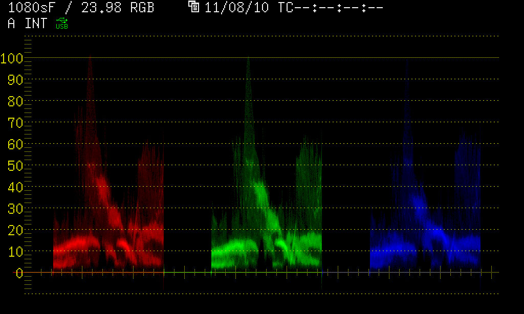
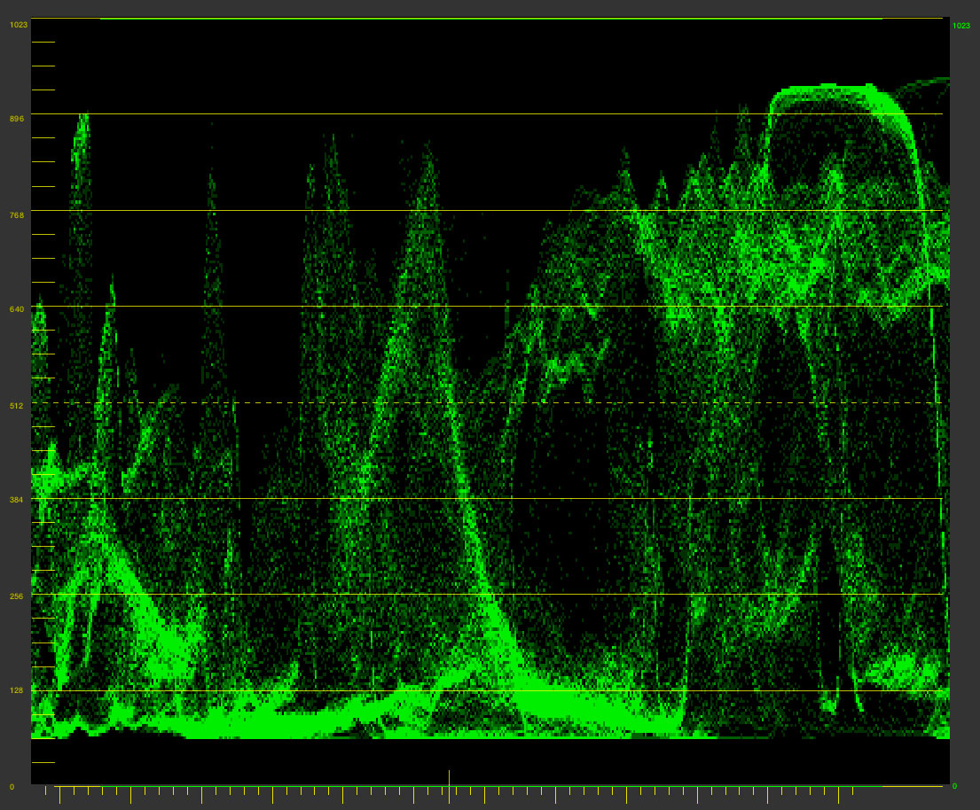
Here's a 50mm Ultra Prime on an Arri Alexa with camera white balance set at 3300 -3, lens iris at T2.8. Below it is an Angeniuex Optimo 24-290mm zoom lens @ 50mm put on the same camera with the same exposure and white balance.

RGAR311338.jpg
ultra-clean.jpg
optimo-clean.jpg
angeniuex_optimo_rental_seatles600x600.png

The Optimo Zoom lens (bottom image) is much warmer and greener than the prime. If these lenses were both working in the same setup, color correction instantly becomes necessary, lest one angle looks "correct" and the other either too warm or too cool in comparison.

All of these variables - optics, light sources, sensors, etc - and their inherently different color temperatures often add up to cameras that don't match and shots within the same scene that are offset from one another along the warm-cool and green-magenta axis.

In this era of high ISO cameras, color temperature offsets are most evident in heavy Neutral Density filters, often used to block as much as 8 stops. In my opinion, heavy ND's are the most destructive variable in contemporary digital imaging. Even with the best available filters such as the Schneider Platinum IRND's, we're still seeing a lot of color temperature offsetting with filters over 1.2. The problem is it seems that most Neutral Density filters (either conventional or with Infrared Cut) do not retard Red, Green, and Blue wavelengths of light in equal proportions. What we're left with after reducing a lot of stop with ND is more blue and green wavelength than red which is vital to the accurate reproduction of skin tones. If this part of the picture information has been greatly reduced, it can be very challenging to digitally push life and warmth back into the subject's skin without introducing a lot of noise and artifacting.

Here's the 50mm Ultra Prime again.

ultra-clean.jpg

And here with a Platinum IRND 1.2. The camera ISO, white balance and exposure are the same. To get the stop needed to compensate for the ND, the quantity of the light was increased on the chart by bringing it closer to not affect its color temperature by dimming or scrimming.

nd12.jpg

Comparing the two, they're really quite close. I've got to say, the Schneider Platinum's are the best I've found. With other sets of IRND's, you'll see significant color temp offset even at ND .3 but with these at ND 1.2, there is only a very slight shift to green. But this is still something that will need to be corrected.

Here's IRND 1.5. We're starting to get increasingly cool and green.

nd15.jpg

IRND 1.8

nd18.jpg

IRND 2.1

nd21.jpg

And for comparison, back to our original, filter-less image.

ultra-clean.jpg

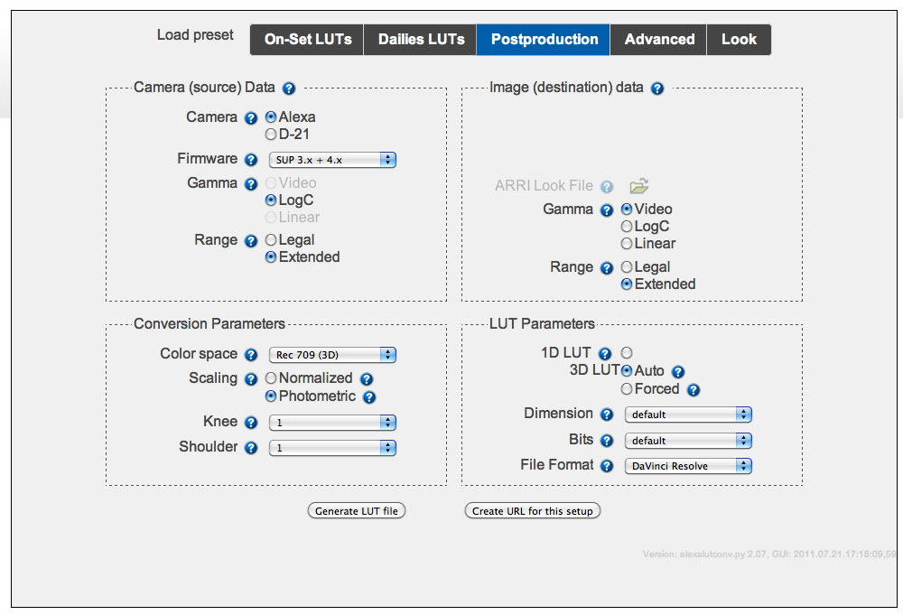
After depriving the image of 7 stops of light with Neutral Density, we've unintentionally reduced some of our red channel picture information. At this point we can correct with camera white balance by swinging the camera to a warmer Kelvin and pulling out a little green. Or we can use digital color correction tools like LiveGrade at the time of photography or DaVinci Resolve in post production to match this shot with the scene. ND filters are but one variable among many when it comes to managing color temperature offsets spread across the camera and lighting.

Fortunately, there are numerous ways to deal with it.

In my opinion, these offsets can usually be solved most expediently with Camera White Balance (WB). Depending on the camera and how we're doing the recording, this WB setting is either "baked in" to the image or exists as metadata. In the case of the Arri Alexa, the orange-cyan (warm-cool) axis is represented in degrees of kelvin with green-magenta adjustable in "+" or "-" points of color correction.

alexa_WB.jpg

If you're working with the RED camera, the Redmote is great for wirelessly adjusting white balance when you need to.

redmote.png

Wireless remote operation of the Alexa is a desperately needed feature. The best we can do for now is the Arri RCU-4 better known as the "Assistant Panel".

rcu_4.jpg

This is a great little device that's chronically underutilized as it gives you full remote access to the camera unlike the Web Browser ethernet interface which is very limited. The RCU-4 is powered through its control cable which I've used successfully at lengths up to 150'. This device makes white balancing the Alexa incredibly fast and efficient as it no longer need be done at the side of the camera.

Not to get too obvious with this.. Moving on.

Another approach is to manage color temperature by putting color correction gel - CTB, CTO, CTS, Plus Green, Minus Green - on light sources in order to alter those with undesirable color temperatures to produce the correct, color accurate response. Color correction tools, digital or practical, do not necessarily apply to the creative use of color temperature. Having mixed color temperatures in the scene is an artistic decision and one that can have a very desirable effect as it builds color contrast and separation into the image. Mixed color temperatures in the scene will result in an ambient color temperature lying somewhere in between the coolest and warmest source. Typically in theses scenarios, a "Reference White", or chroma-free white can be found by putting the camera white balance somewhere around this ambient color temperature.

Identifying problematic light sources and gelling them correctly can be a very time and labor intensive process and one that doesn't happen on the set as often as it should so is usually left up to the digital toolset. There is now a whole host of affordable softwares that can be used on the set at the time of photography like LiveGrade or LinkColor or later in post production - such as Resolve, Scratch, Express Dailies, and countless others.

When we're talking about On-Set Color Correction, we're usually talking about ASC-CDL or Color Decision List. CDL is a very useful way to Pre-Grade or begin color correction at the time of the photography. This non-destructive color correction data is very trackable through post production and can be linked to its corresponsing camera media through metadata with an Avid ALE. When implemented successfully, the Pre-Grade can be recalled at the time of finishing and be used as a starting point for final color. In practice, this saves an enormous amount of time, energy, and consequently.. $$$.

Here's one way an ALE with the correct CDL information can be generated in Assimilate Scratch Lab:

In the top level of Scratch, here's our old friend the Chip Chart. Hooray!

scratch_top.jpg

We've applied the standard Alexa Log to Video 3DLUT to these shots and as you can see, the first one looks pretty good but the rest suffer from various degrees of Color Temperature Offsetting.

s1.jpg
s2.jpg
s3.jpg
s4.jpg

At this point, if we Pre-graded on the set, we could load the correct CDL for each shot and be ready to output dailies.

In the bottom lower left on the Matrix page, is the LOAD button. Click it to go to this dialog window:

load_cdl.jpg

Here CDL from the set can be applied on a shot by shot basis. Once everything is matching nicely it's time to embed this work into metadata that can easily be tracked and recalled at a later time.

CDL_Export1.jpg

Select +CDL and click "Export EDL/ALE"

cdl_ale.jpg

From the drop-down, select .ale, and then name your ALE something appropriate.

Now in Avid Media Composer, we're going to import this ALE to add ASC-CDL Slope, Offset, Power, and Sat (Gamma, Lift, Gain, and Saturation) values that will now be associated with their corresponding clips.

This post assumes a working knowledge of Media Composer. If you're not sure how to set up an Avid project, import media, make bins, and import an ALE, there are plenty of great tutorials out there.

Once you have the transcoded DNxHD media in the correct MediaFiles directory, import the ALE.

choose_columns.jpg

Click the "Hamburger" Icon in the lower left of the bin (I have no idea what this Selector tool is actually called but I've heard many an Assistant Editor refer to it as the Hamburger), and then select "Choose Columns".

bin_columns.jpg

Here we have the opportunity to select which columns show up in our bin. The ASC-CDL values are already embedded in the ALE we imported but it's a good idea to verify them which we can do at the bin level by turning on these columns. From the "Choose Column" drop-down, select ASC_SOP (Slope, Offset, Power) and ASC_SAT (Saturation).

asc_sop_sat.jpg

As you can see, all of the adjustments we made as CDL are now reflected in numeric values and are linked to their corresponding shot in the form of Avid metadata. ASC-CDL, while unfortunately limited in a lot of ways, really is a fairly univeral interchange for color correction data and can be implemented quite easily.

What we really need is a way to recall these ASC-CDL values from the ALE in a software like LiveGrade making this color correction data even more interchangeable.

Another possible workflow is to generate the dailies in Resolve using CDL from the set. Once that CDL corresponds with a shot in Resolve, that CDL can track with its correct shot all the way to finishing if the original Resolve project(s) is used.

What's the best approach? All of the above. The right tool for the right task and no two projects are alike. That's why a DIT is hired in the first place, to consider the criteria and then advise the best course of action. 

Update

on 2013-06-06 14:55 by Ben Cain

Just read this related article -

http://www.hdvideopro.com/technique/miscellaneous-technique/help-desk-getting-it-white-the-first-time.html?utm_medium=referral&utm_source=pulsenews&start=1

Content feels eerily familiar!

Cutting the Cord

IMG_1160.jpg

Cutting the Cord

January 17, 2013

First post of 2013. I'm writing this on an overnight train. God bless free wifi. Here we go.

Someday we might look back at the time when we were forced to use masses of chaotic, unruly conduit with a certain nostalgia. But then likely be glad those days are long behind us.

Wireless HD = no cable between the camera and video monitoring. Instead we have a transmitter (Tx) on the camera coupled with a receiver (Rx) on the monitoring end that captures the 1920x1080 video signal out of the air and outputs it via HD-SDI to our on-set video system and/or monitors.

Wireless HD is finally here in a big way but with so many options now available, more on the way, and at so many different price points, which system is the right fit for your needs? This depends on many factors but among the current crop, don’t expect to find the perfect solution. At least not just yet.

Amazing breakthroughs have been made in this technology as the equipment is getting smaller, lighter, and capable of far greater range yet each product offering presents a specific set of advantages and disadvantages. At this time, the “perfect” wireless HD-SDI video system would have the following features:

Video output from Rx: 1920x1080, Uncompressed, 10 bit, 4:2:2, SMPTE 292M 1.485 Gbit/s HD video with embedded audio and timecode.

That is, a video carrier from the wireless system that is identical to which is delivered over standard 75ohm BNC cable -

“the transmission of uncompressed, unencrypted digital video signals (including timecode, audio, and metadata) within television systems”.

Really, 3G-SDI 444 SMPTE 424M 2.97 Gbit/s HD Video is preferred but this standard is not yet universal for on-set monitoring so 422 will suffice.

Zero Latency (no delay). As we’re almost always in a double system production environment, meaning picture and sound are recorded separately. For the purpose of on-set monitoring as far as video village is concerned, video and sound need to be in perfect sync. In a wireless system with latency, that is one with frame delay, picture will lag behind sound so presents a problem for those evaluating actor performance, etc. at video village. Our perfect wireless video system is one without a single frame of delay.

Small physical footprint. Ideally the Tx is small, light, unobtrusive, and can be easily powered from the camera without drawing excessively. It should be mountable in several ways and shouldn’t get in the way of the assistants or operator. This goes for the Rx as well. It should be small as it will often need to be hidden so as not to be seen by the camera(s). It needs to be mobile, easy to set up, easy to power, and most importantly – mountable to a stand as its position will change constantly in search of the best connection with the Tx.

Ease of operation. No overly complicated menus please.

Signal quality. The ideal wireless system would output a signal of no different quality than what comes through a video cable. Unfortunately, the technology isn’t quite there yet but several of these systems are very good. The wireless signal needs be very high quality and at great distances. The longer, the better. Again, this is something that is improving but in general, the range one gets with all these systems is never quite  what you need and the greater the distance, the more degraded the signal. In a perfect world, the range would be so good that the Rx could live on the DIT or Video Assist Operator’s cart and never have to be moved. Unfortunately, this is not the case at all. The Rx will likely need to be mounted to a stand, positioned high in the air, and placed within a clean line of sight of the Tx to create an acceptable video link.

This point of signal quality proves to be the most problematic if we’re hoping to use the wireless signal for engineering purposes, that is – image evaluation, quality control, real time camera painting, and the creation of useful color correction data to be put into the post production pipeline. In order to do this we require a very robust signal. In my experience, you can accomplish certain engineering tasks wirelessly but it’s less than ideal as trying to create a wireless image of high enough quality can be a time consuming and occassionally futile process.

Not one of these existing wireless solutions can claim to satisfy all these points perfectly but several of them do a good enough job under the right circumstances.

The ultimate goal of wireless HD video technology is to replace the physical video cable between the camera and monitoring with a wireless alternative of equal quality. We’re getting closer all the time. Let’s explore some of the current options.

FIRST - WHY GO WIRELESS?

So many reasons.. But here are a few in no particular order.

I know the cables in my rack work. I know the cables feeding my monitoring and looping through my hardware work. I know this because I routinely test and remove faulty cables. Because I know my stuff works, if there are video system errors, 9 times out of 10 it’s because of a rental house cable tied into the camera. Or a bad BNC barrel. Or a failing cable harness. In other words, the problem is likely at or near the camera and intermittent signal indicates a defective cable somewhere in the chain. Quickly identifying where though can be problematic. If I have only one short cable feeding my Tx directly from the camera’s HD-SDI port, the chances of cable related signal problems have effectively been eliminated.

Going wireless saves enormous amounts of time and energy. Cabling multi-cam can be a challenging task requiring a lot of cable and lots of hands on deck. As cable runs get longer, barrels are introduced which are notorious for failure. Additionally, any run longer than a few hundred feet will require a repeater. Setting all this up and trouble shooting inevitable problems takes time, time that should be, but is rarely available on set. All that cable is heavy, takes up a lot of room on carts, and requires a person(s) tasked with safely and efficiently running it out and pulling it back for every setup. Ideally a dedicated Utility person would do this but having that crucial extra set of hands is unfortunately not always available to the camera department. You can thank diminishing production budgets for this. The beauty of wireless is that as long as the cameras are powered up, they are always transmitting. And as soon as DIT is ready to go, there’s an image to start working with. In practice, wireless is a godsend to an understaffed camera department.

Video cables are a filthy occupational hazard to our job, especially here in New York City. I’m sure many readers can attest to how often they’ve been on location in the middle of the night pulling up hundreds of feet of cable from toxic Manhattan gutters covered in dog by-product, antifreeze and motor oil, garbage juice, and god only knows what else. I don’t wish this task on anyone and regardless of work gloves, regardless if cabling is “someone else’s job”, it’s extremely dirty work and a wireless set is a more sanitary set. Granted, because of the current limitations of the wireless equipment, cables still must be run to the Rx. However, these runs are typically far shorter and usually involve a single cable so this practice is definitely more efficient.

CURRENTLY AVAILABLE WIRELESS HD VIDEO SYSTEMS:

I’ve used most of these products fairly extensively so can speak to the nuances of their operation - where they excel and where they fall flat. I’ll also disclose now that I am a Boxx Meridian owner/operator so do have a vested interest in these though I’ll be the first to admit they can be frustratingly finicky. The point that I’ll make again is that wireless HD video is an emerging technology and is far from perfect. There are major shortcomings preventing any of these systems from being the perfect solution for what I’ve proposed. The wireless set CAN be accomplished but be aware that for now, ditching the video cable just trades one set of problems for another. 

BOXX MERIDIAN 

boxx3.jpeg

“Boxx provides Digital Microwave Transmissions at a fraction of the cost of traditional COFDM systems.”

The science behind this technology is fascinating and something that I’ve been learning about though osmosis but not one that I’m particularly well versed in. For the purposes of this blog post, it’s relevant but not impactful enough to warrant the time it would take to really get into this. But here's some info if you're interested.  

An explanation of Coded Orthogonal Frequency-Division Multiplexing (COFDM)

Vs.

Digital Microwave Transmission which is the technology utilized by the Boxx.

The Boxx Meridian (Boxx) has been around for quite awhile and is still likely the production’s first choice for wireless needs. At the heart of the Boxx is a modular antenna system in which different versions can be connected to the Rx depending on how demanding a range is required. These antennas run the gamut in size and price but this standard high gain antenna is widely used and is what I have on all my systems.

boxx1.jpeg
boxx2.jpeg

For the most part, I’ve had great results with it. I recently did a feature film that required free roaming cameras, seeing 360 degrees, and traveling up 600 feet within one shot. The photographic demands of this project would have been impossible without the Boxx and the systems performed remarkably well which allowed us to focus on imaging and not shot logistics. 

THE GOOD:

Very solid construction. Even damaged, the equipment still works.

IMG_3315.JPG

The Tx was smashed doing a vehicle shot but it still worked fine even with the interface rendered inoperable. Boxx is tough.

The Tx and Rx are the same size. Tx easily fits on camera in-between battery and camera body. It comes standard Anton Bauer but can be adapted to IDX. Both the Rx and Tx are 6.5-18v DC and can be powered with a variety of accessory cables. In my experience, the Boxx Tx is the easiest wireless transmitter device to power on camera. Rx can be outfitted to several antennas depending on range needs (see website for details). With the high gain antenna, in the right conditions I’ve experienced incredible ranges around 600 feet. We’ve shot boat to boat, vehicle to vehicle, and helicopter to land and generally had great results. Users of Boxx Meridian systems have even reported going building to building in Downtown Manhattan. Granted signal quality is substantially degraded at these distances but as long as the transmission is strong enough to be detected by the Rx, it will output what’s available. The image doesn’t always need to be pretty; sometimes what’s most important is to just get an image up by any means necessary. The Boxx excels at this.

The Tx and Rx are switchable between a number of different frequencies which is useful if you’re in an area with a lot of RF contamination and are experiencing poor signal. Additionally, you can use this functionality to gang multiple receivers to a single transmitter.

It is a zero latency, zero delay system. Using the Boxx, dual system audio will sync up perfectly with picture at video village / client monitors.

The Rx is extremely mountable and easily powered with Anton Bauer or IDX with an adapter. The antenna is physically bright white and big enough to be seen in the background though which can be problematic when needs to be hidden in a multi-cam scenario. 

A VERY IMPORTANT QUESTION - CAN YOU PAINT THIS VIDEO SIGNAL?

That is, can you generate accurate color correction data using this wireless video signal? The answer is yes you can to a certain extent. The Boxx Meridian outputs an uncompressed, 10 bit, 4:2:2 video signal that is compliant to SMPTE 292M. The carrier is identical to a cable based signal. Successful wireless camera painting is of course entirely dependent on signal quality and if an acceptable image cannot be achieved then making critical color and exposure decisions is not advised. At it’s worse though, the Boxx’s transmission quality has little effect on video color (chroma). You are much more likely to experience signal degradation in the form of a softer, grainier image along with a little macro blocking and other artifacts. The best case scenario with the Boxx, you can’t even tell you’re wireless. However finding a frequency that will allow for this can be a tricky and time consuming endeavor. The equipment is also prone to many difficult to troubleshoot environmental conditions and sometimes it can be difficult to get the best image for the situation. “Wireless engineering” with Boxx Meridian is a judgment call.

THE NOT SO GOOD:

These systems aren’t cheap. A basic kit will set you back around 18,000 USD.

The number one problem with the Boxx Merdian though lies in the Tx. This unit does not have any reclocking signal amplification hence no loop-thru SDI which is a badly needed feature. Because the signal is not amplified in the Tx, if a degraded signal from say faulty cable is input, the user will almost certainly experience transmission problems. I’ve experienced this numerous times with techno cranes and vehicle rigs where it was impractical for me to mount the Tx on the camera. Long runs of cable full of barrels (the cable you’ll find in the arm of a crane!) will not provide a strong enough signal to the Tx for successful transmission. Because of this lack of signal amplification, the Tx is very prone to all input cable related problems. Whatever cable feeds the Tx from the camera needs to be as short and as new as possible. Worn cables can present a problem. Also, BNC elbows are not recommended for the same reason. Knowing this shortcoming can help you troubleshoot inevitable connection issues that will arise between the Tx and Rx.

The Boxx Meridian can transmit, receive, and distribute HD Component, HD-SDI, SD-SDI, and Composite video. It can be switched between PAL and NTSC and can input and output all standard SMPTE video formats. I put this in NOT SO GOOD because at this point, all we're using is HD-SDI. Having all these other inputs just adds unecessary cost and weight to the system. 

The standard high gain antenna (see image above) is housed in quite a flimsy plastic which is very easily damaged. It’s also blinding bright white which makes hiding it from the camera problematic.

You gotta get creative.

d485b44a195e11e2a44612313813206e_7.jpeg
2bfaf1321a1c11e2baac22000a1f975b_7.jpeg

In my experience working with these on an almost daily basis, I think they’re pretty good. Not perfect, but reliable enough. I have occassionally encountered serious frequency problems but the success I’ve had with them far outweighs any time lost to troubleshooting. In practice, you can count on a good strong signal 150-200 feet. Any range greater than that is very much more subject to environmental conditions.

NEBTEK MICROLITE

From Nebtek >>>

micro-6__77876_zoom.jpeg
micro-3__59920_zoom.jpeg

The Microlite from Nebtek is a very impressive COFDM based system that has been available for about a year now and is very popular with Video Assist / Playback Operators. The Microlite's incredible range is it's strongest feature. 

THE GOOD:

The Tx is tiny, unobtrusive, uncluttered with unnecessary inputs, easy enough to power, and as mentioned, the range is incredible - about twice what you get with the Boxx. I refer to the Microlite as my “get out of jail free card” and have used it in multi-cam situations where there’s enormous distances between cameras, or where one camera splinters but stays within range.

The Rx is small, mountable, and easy to power with either Anton Bauer or IDX batteries. Power draw is very low.

Tx and Rx can switch between 12 channels. This can be used to find the optimum frequency for a particular environment or to gang multiple Rx to one Tx.

THE NOT SO GOOD:

The kit costs about 20,000 USD.

Most importantly, the Microlite is NOT an uncompressed wireless system. It achieves such incredible range by encoding into a more efficient H.264 carrier and is then transmitted. It is decoded up reception and then output as HD-SDI video. As far as the video engineer is concerned, this introduces two problems –

The first being latency. The process of encode, transmit, decode introduces a noticeable frame delay. Video that has gone through the Microlite will lag behind sound so will not be in sync at Video Vilage. For some, it’s an acceptable amount. For others, not so much. One solution to this is to delay audio to meet the delay in video but this is not something I’ve seen implemented.

The second problem with the Microlite for the video engineer is that this compression introduces a bit of contrast that isn’t in the actual signal. Picture processed through the Microlite is slightly punchier than if displayed over a video cable or through an uncompressed system like Boxx. Highlights tend to look a little more blown out than they actually are and shadows appear darker with less detail. Additionally as the Microlite wireless signal is degraded over longer distances, it gets warped, delayed, and chroma shifts. For this reason, critical quality control and camera painting using the Microlite is not advised. This is equipment is intended strictly for monitoring only.

In keeping with my earlier statement – many times, what’s most important is to just have an image on the monitor regardless of quality and in these challenging situations, the Microlite is an extremely valuable tool.

TERADEK BOLT

Bolt site >>>

bolt_sizes.png

THE GOOD:

The Bolt is brand new and still trickling out to market. I pre-ordered so have had a system for about a month and have been testing.

These are cheap - the “Pro” system has a built-in L-ion battery that will power the Tx for 90 minutes, is only 2490 USD. This includes the dual ouput Rx and a few power cables.

The Bolt is tiny. And so light, the operator won't even know it's there. 

The Bolt is the only HD wireless video Tx that has a HD-SDI Loop Thru. The Bolt is a 3G-SDI, Uncompressed, Zero Latency wireless system and Teradek claims ranges of up to 300 feet.

So uncompressed, zero delay wireless HD for 300 feet for 2490 USD? There must be a catch right? 

THE NOT SO GOOD:

First off, and I always find cases like this to be interesting, I’m not entirely convinced the manufacturer knew how the Bolt would actually be used on the set as there are some puzzling power and ergonomic issues.

The power draw is mismatched as the Tx is 6-12v and the Rx is 6-28v. In all other wireless video systems, both Tx and Rx are 12v and easily battery powered. In the case of the Bolt, both Tx and Rx have 2pin Lemo inputs but the kit only comes with one Anton Bauer P-tap to Lemo cable. Because Lemo is a common connector, custom cables can be made easily enough but this is a bit of a pain. Given the cables that come in the kit, they assume your camera has a P-tap output (the Alexa’s battery plate does not!) and that you will power the Rx from an AC outlet using the included 2pin Lemo to AC Adapter. I’ve never been in a situation where powering my wireless Rx with AC was even remotely practical. If you're wanting to power the Bolt Rx with a battery, and you will, you’re going to have to get creative. 

Mounting the Tx and Rx. The Tx has a 1/4-20 receiver so is mountable enough on smaller cameras but on the Alexa in studio mode, your only real option is mount it with a cine arm. Or..

bolt.jpeg

..find a place to wedge it in. 

The Rx has a 1/4-20" receiver as well though it requires a threaded thumb screw that is included in the kit. 

Bolt_RX_1-4-20_mount.jpeg

In practice, with any wireless video system Rx placement is crucial. This is why most available systems have very mountable, very easily powered Rx that can be placed on a C-stand wherever it needs to go for the best connection with Tx.

Here's the Bolt working in (relative) harmony with the Boxx.. mounted on a stand of course.

bolt2.jpeg

So in order to start testing, I had to get creative. I had Steven Zuch Enterprises custom make me the cables I needed. I got an additional P-tap to 2pin Lemo (because one is never enough) and because I’m working with Alexa, a 2pin Lemo to 2Pin Lemo to power the Tx from the camera’s 12v output. For the Rx – it can be powered off an Anton Bauer battery via the P-tap to Lemo cable. But how to get it onto an Anton Bauer battery plate? And then how to get the whole contraption onto a stand?

This is what I came up with using spare parts from B&H.

69203.jpg
33214.jpg

The Universal Anton Bauer Gold Mount Battery Plate can be dual locked to this Matthews Mounting Plate with 5/8" receiver. This setup will allow the Bolt Rx to be both battery powered and mountable to a standard C-stand. 

First attempt - I velcored the Rx to the battery but came back after an hour to find that it had melted off so I ended up just using a bongo tie to keep it all together. Not the most elegant solution but it works.

bolt1.jpeg

The next issue, and one that I’m in the process of looking into, is the Bolt outputs some sort of irregular video signal. It is uncompressed but it’s not standard to SMPTE. Blackmagic Designs video hardware doesn’t like this output and won’t recognize it. Additionally, the Raptor Playback system won’t recognize it so if this is what your Video Assist Operator is using, there will be dark screens at video village. In a situation like this, the Bolt can’t be used unfortunately. I’m currently out of the country so haven’t been available to fully dig in and figure this out. I’m curious to run its output through a Decimator MD-DUCC..

Decimator_MD_DUC_4e2c19af915b5.jpeg

..and see if it could be used to get the Bolt output into a more normal video signal.

UPDATE 1/19/13: Teradek is aware of the issue and working on firmware to resolve. 

And most importantly - range and image quality. The image quality is really quite good with the Bolt. Similar to what you get with the Boxx in that degraded signal will look grainier and grainier until it just cuts out. I found the Bolt’s range to be pretty reliable at 50-100 feet but this is with of course with getting the Rx into an ideal position in relation to the Tx. Anything beyond 100 feet signal quality is substantially degraded and I could not get a connection at 200 feet. Evaluating the real range capabilities with all these systems though is difficult as all experience problems and are subject to environmental conditions.

Each pair of Bolt Tx and Rx are married to a single frequency at the factory. This means that you can’t change the channel to find a better frequency. However, the pair will automatcally jump to another channel if too much interference is detected. 

I don’t think the Bolt is nearly as robust a system as the Boxx or the Microlite. Its performance shows promise but there are a lot of workarounds to make it functional in a real production environment. But it’s also 1/10 of the price of the more expensive units. If no on-set video other than say, a director’s monitor is required, the Bolt might be a good fit. This seems to be its intended use.   

I’m still trying to figure out how I’m going to use these. Perhaps as a backup for the Boxx. Or assuming there is a way to normalize the signal, it’s potentially a great way to get video to a handheld director’s monitor or even to transmit wirelessly to video village. That would actually be ideal. The Bolt has potential but so far, I won’t be able to use these as a replacement for my other wireless systems.

BOXX ZENITH

Product site >>>

Boxx Zenith.jpeg

The Zenith wireless system is designed for wireless ENG and HD live productions where range and signal reliability are essential. The unique network capability of the system allows for an almost infinite shooting area by deploying inexpensive receiver nodes wired with Category-5 cabling. Inexpensive repeaters can be created to bounce signs around corners.

The bandwith is adjustable (between 5-40MHz) and one of the strengths of the Zenith system is its ability to navigate around interference when operating in “wide-bandwith mode” making the link robust and extremely stable.

Zenith is fully configurable via a Web interface and statistics can be monitored on portable devices allowing the operator the flexibility to configure either system from a laptop for optimal HD wireless transmission within any environment. Zenith provides a scalable modular solution allowing trade offs between budget and performance. 

New to market so have not had a chance to test. This seems to be Boxx’ answer to Microlite – a compressed system with latency but with incredible ranges. 

IDX WEVI / CAM WAVE

Product site >>>

28268970.jpeg

Not really worth discussing in my opinion. This is late model technology though they are still in use. The range is terrible as is the signal quality. These are affordable at 3549 USD. The Tx is large and the Rx is not nearly as mountable as the Boxx or Microlite.  

PARALINX ARROW

Product site >>>

Paralinx-Arrow.jpeg

This is an HDMI based wireless system that was intended for use with HDSLR’s. It was not intended for any serious monitoring other than perhaps to a single display within a very short distance of the camera. It serves no purpose for the needs of the DIT or Video Assist Operator working in larger production environments. The price is $1199.

ABELCINE WIRELESS VIDEO SOLUTION

Product site >>>

abelwire.jpeg

I have not used these but am curious. Perhaps Andy would give me a demo sometime. 1499 USD.

ANTON BAUER AB-HDRF

Product site >>>

ABHDTX_IKE.jpeg

Catchy name. Have not used. 21,599 USD.

SWITRONIX RECON

Product site >>>

200078026_640.jpeg

Have not used. Price and ergonomics seem similar to the WEVI. 3095 USD.

TRANSVIDEO TitanHD

IMG_4545.JPG

From Transvideo site >>>

State-of-the-art Digital HD/SD wireless transmission system

  • Ideal for video-village, news, sport, digital-cinematography and body-rigs

  • Latency bellow 5ms

  • Accepts HD/SD SDI, composite & HDMI

  • Low power consumption

Transmission Range

The transmission range varies depending on the topology of the location, performance remained excellent within an open field line of sight test from 200 feet (60 meters). It can be reduced by walls or interferences with other systems.

Audio & Metadata Transmission

TitanHD includes audio transmission where 2 channels are embedded in the SDI signal or 2 analog balanced inputs. SDI embedded Timecode and Tally transmission are possible in place of one audio channel (if any embedded in the SDI). Several other possibilities are available to remote basic functions (Tally and GPIO).

Link

The selection of a channel can be manual or automatic. In P2P mode the link is possible only between one receiver and one transmitter. In Broadcast mode up to 6 receivers can be linked to a single transmitter, but data transmission from receiver to transmitter (S/N ratio, GPIO) is not possible.

I have not used this product. Key features - Low latency and HD-SDI Loop Thru at 9085 USD. 

BMS - BROADCAST MICROWAVE SERVICES

The BMS company offers a wide and diversified product line for Government, Surveillance, Law Enforcement, and of course Motion Picture Filmmaking ;)

BMS DR25xxHD

Broadcast-061.png

With wireless Video Assist solutions from BMS, waiting for dailies is a thing of the past. Using license-free 5.8GHz COFDM wireless technology, BMS can transmit live footage in almost any environment with a delay as low as 40ms (one frame). This low-latency, high definition capable system allows directors and crews to see the action as it happens, just as the viewer will see it.

Powered by the lightweight, compact NT5723SDHD transmitter, the Video Assist system offers the closest substitute to a wired camera available. The DR2558HD receiver offers a small, easy to operate receive station that outputs SDI at standard or high definition. The DR2505HD offers the same capability, plus additional amplification to allow for distant antennas, potentially increasing reception range.

A smaller, Nano version of this system is also available. 

I have no expereince with these wireless systems and have not been able to locate any pricing on them.

TERADEK CUBE

Product site >>>

jag35_teradek_cube008.jpeg

The Cube is an interesting product. It is not intended for any real serious monitoring as it is wifi based so is heavily compressed with lots of latency. It is mostly used to impress clients on commercial shoots so they can watch on their iPads. Prices vary but the HD-SDI kit is 2690 USD.

RED MEIZLER MODULE

Product site >>>

1347115714.jpeg

Coming to market. 13,000 USD. The RED Meizler Module is a very progressive piece of gear and I’m curious to see how it will hold up in terms of range, signal quality, and overall reliability. While this functionality isn’t built directly into the RED camera, I’m guessing most owner/op’s will buy these so many RED sets will become wireless by default. To RED’s credit, building this functionality into their flagship product is very forward thinking. Just as the Alexa Plus and Studio have wireless lens control built-in, perhaps Arri’s next camera will include HD video transmission as well.

WIRELESS VIDEO SERVICE:

RF FILM

Company site >>>

RF Films is a company providing state-of-the-art wireless video technology as a production service. I’ve never worked with this company but have heard the ranges and quality is incredible. Each system comes with a dedicated microwave technician and distances of up to six New York City blocks have been reported. I’d like to learn more about this service and how it works. 

There are of course, even more options available and more coming soon so if you would like to add anything to this post, please email me (bennettcain@gmail.com).

Disclaimer - In best practice, the smartest and safest way to do color critical quality control is always over a video cable so if this work is to be attempted wirelessly, using any system, proceed with caution.

THE FUTURE:

Moving forward, it’s my hope we continue to see less and less cable on the set and equipment footprints that get smaller and smaller. I’m of the opinion that less is more and am always striving to streamline and simplify. In the case of video cables, fully wireless sets can’t come soon enough as far as I’m concerned.

Regarding the wave of higher-than-HD resolution cameras we’re about to be bombarded with:

As is the case for existing RED and Arriraw workflows - a 1080 video on-set workflow combined with in-camera evaluation tools - will tell you just about everything you need to know about the imaging. We’ve been working this way with these high-resolution cameras for years now and have been doing just fine. I await with bated breath the inevitable marketing storm that will say the ONLY way to work with these cameras is to monitor and scope in 4K. Our existing video infrastructure, monitoring, and evaluation tools are firmly entrenched in 1080 video and to rebuild all of that industry wide will take time and capital. Additionally, higher than HD resolution monitoring is currently excessively large, expensive, virtually nonexistent, and difficult to work with as it can require up to 4 cables from imager to display. All of this will change of course but I’m quite certain we’ll be working with 1080 video on the set for some time to come. It's my opinion that these wireless video systems will continue to be viable for the foreseeable future.

HEALTH RISKS:

I would be remiss if I didn’t mention the potential, and supposed, cancer risk involved with being bombarded with ultra high frequency RF. The problem is at this time the data is hugely inconclusive. Any one of these vendors will tell you it isn’t much worse than talking on a cell phone for a few hours a day. But this is exactly what one would expect them to say. And just like the debate on the safety of cell phones, no one can say for certain just how dangerous, if at all, these wireless video systems really are. This is quite a problem and I’ve had a many a discussion with nervous camera operators who would prefer not to have a wireless video transmitter by their head all day or in the case of Steadicam, by their groin. I can’t say that I blame them. It is definitely something to be aware of.

If you're interested, here is the follow up to this article >>>

Arri Alexa - Legal vs. Extended

Arri Alexa - Legal vs. Extended

August 1, 2012

While this article is very specfic to the Arri Alexa and its digital color workflow, in a broader sense much of the information here can be readily applied to the difference between YCbCr 422 digital video, RGB Data, and all the things that go wrong when we monitor in video but post process RGB Data.

That said, here we go.. 

Anyone doing on-set color correction for the Alexa is well acquainted with the LogC to Video LUT workflow. I'm guessing many of the readers of this blog are already savvy but just in case, here's a refresher -

First a definition - "Log C" is a video recording option on the Alexa and stands for "Log Cineon". This encoding scheme is based on the Kodak Cineon Curve and it's purpose is to preserve as much picture information as the sensor is able to output.

Here's Kodak's Cineon (Log) encoded LAD test image (screengrab from LUT Translator software) -

cineon_log.jpg

Log encoding is most evident in the form of additional latitude in the shadows and highlights that would be lost with a traditional, linear video recording. A log encoded recording results in images that are very low contrast and low saturation, similar in quality to motion picture color negative scanned in telecine as this is what Cineon was designed to do. This unappealling Log image will inevitably be linearized using a Lookup Table (LUT) into something with a more normal or, "video", level of contrast and saturation.

Kodak Cineon LAD image, now linearized with a 3D LUT:

cineon_linear.jpg

All LUT's take input values and transform this data into an output. In the case of Arri Alexa LUT's we input Log C and output Rec.709 Video. In this workflow, the terms "Video" and "Rec.709" are used interchangeably. Rec. 709 is the color space for HDTV and all the color correction we're doing in this workflow is within this gamut.

Rec.709 Gamut

Lookup Tables come in 2 flavors - 1D or 3D. 

From Autodesk glossary of terms:

1D LUT:A 1D Look-up Table (LUT) is generated from one measure of gamma (white, gray, and black) or a series of measures for each color channel. With a pair of 1D LUTs, the first converts logarithmic data to linear data, and the second converts the linear data back to logarithmic data to print to film.

3D LUT:A type of LUT for converting from one color space to another. It applies a transformation to each value of a color cube in RGB space. 3D LUTs use a more sophisticated method of mapping color values from different color spaces. A 3D LUT provides a way to represent arbitrary color space transformations, as opposed to the 1D LUT where a component of the output color is determined only from the corresponding component of the input color. In essence, the 3D LUT allows cross-talk, i.e. a component of the output color is computed from all components of the input color providing the 3D LUT tool with more power and flexibility than the 1D LUT tool. See also 1D LUT.

LUT's are visualized by "cubes". Consequently, 3D LUT's are often referred to as cubes as well.

Here's a cube representing a pre-LUT image (from Pomfort LiveGrade):

log_cube.jpg

And the same image, linearized by a 3D LUT:

linear_cube.jpg

And an example recorded with the Alexa camera: the Chroma du Monde in LogC ProRes 4444 to SxS. 

cdm-log2.jpg

And the same image, its color and tonality transformed into more normal looking HD video, with a Rec.709 3D LUT from the Arri LUT Generator

cdm-linear2.jpg

Summary of a possible LogC to Video on-set workflow:

1. We feed a Log C encoded YCbCr (422) HD-SDI video signal out of the camera's REC OUT port into...

2. our HDLink Pro, Truelight Box, DP Lights, Pluto, or whatever color management hardware we happen to be using. 

3. We then load the hardware interface software - LinkColor or LiveGrade for the HDLink Pro or the proprietary software for our other color management hardwares. 

4. Using our software, we do a real-time (that is, while we're shooting) color correct of the incoming Log encoded video signal. Through the use of 3D LUT's we non-destructively, i.e. the camera's recording is totally unaffected, linearize the flat, desaturated Log image into a more normal looking range of contrast and color saturation. On-set color correction, herein referred to as "Camera Painting" for the purposes of this article, has the option of being applied either pre or post linearization that is before or after the 3D LUT aka, "DeLog LUT" is applied.

This selection is known as Order of Operations and it's very important to establish this when working with a facility such as Technicolor/Post Works or Company 3/Deluxe to generate the color corrected production dailies. In the two most widely used on-set workflow softwares, LinkColor and LiveGrade, the user can specify this Order of Operations.

Painting Pre-Linearization in LiveGrade:

prelinear.jpg

And painting Post-Linearization in LiveGrade

postlinear.jpg

Toggling between pre and post painting in LinkColor:

lctoggle.jpg

I'll get more into the differences between working pre or post but for now, simply take note that it's an important component of any on-set color color correction workflow, the ultimate goal of which is to close the gap between the work done on set and in post. 

5. After linearzing and painting the Log encoded video signal, we display the pleasing results on our calibrated Reference Grade Monitor (the most important component of working on-set) for evaluation and approval by the Director of Photography. We can also feed this color corrected video signal to video village, client monitors around the set, the VTR Operator or whomever else requires it. 

6. Additionally, the color correction data we create through this process can be output in the form of 3D LUT's and/or Color Decision Lists (ASC-CDL) to be applied to the camera media in software such as Scratch Lab (which I use and recommend), Resolve, Colorfront OnSet Dailies, YoYotta Yo Dailies, to create color corrected production dailies - files smaller in size than the camera master to be used for review, editorial, approvals, or any number of other purposes.

This final step I've outlined will be the focus of the article you're reading - how do we create color correction data on the set that will "line up" with our camera media in post production software to create dailies files that look the way they're supposed to look. 

Anyone who has done this work has encountered bumps and occassionally chasms in the road along the way. All parties - DIT's, DP's, producers, dailies colorists, and post production facilities are becoming more experienced with the workflow so the process is getting easier.

What I've found to be at the root of the problems you'll likely encounter though is a matter of nomenclature and the confusion that comes from the exact same terms essentially having different meanings in video production, that is YCbCr 422 digital video, and post production where we deal with RGB Data. Fortunately once a few points are acknowledged, this hazy topic comes into sharp focus. 

At the very beginning of the workflow we have three options for the Log C video output level on the camera's REC OUT channel - Legal, Extended, and Raw. For the purposes of this article, only Legal and Extended are of concern (image from Alexa Simulator). 

alexaout.jpg

Our recording, be it ProRes 4444 to the camera's on-board SxS cards or ArriRaw to an external Codex, OB1, or Gemini, will be Log C encoded so the monitor path we're going to paint will also be Log C. This workflow is recording agnostic in that it's not specific to ProRes, ArriRaw, or Uncompressed HD though you may use the camera's outputs differently depending on the recording. 

In the on-set camera painting ecosystem we have the following variables -

1. REC OUT camera output levels: Legal or Extended

2. Arri Log to Video Linearization 3D LUT choice: Legal to Legal, Legal to Extended, Extended to Legal, or Extended to Extended. Note: while you certainly can use any LUT of your choice as your starting point, even one you custom created, these Arri LUT's are universally used in Alexa post production and in most dailies software so by using them on-set, you're one step closer to closing the gap. An exception to this might be starting your painting with a specific film emulation LUT as specified by the post production facility. 

3. Software Scaling: In softwares such as LinkColor and LiveGrade we're able to scale our incoming and outgoing video signals to either Legal or Extended levels on top of any scaling we're doing with 3D LUT choice and/or camera output levels. 

The combination of these 3 variables and their choice between Legal orExtended, all of which will either expand or contract the waveform, will result in wildy different degress of contrast. Understanding scaling and acknowledging that is inevitable when transitioning between video and data is the key to creating a successful set to post digital color workflow. The ultimate goal of which is to create color correction data that when applied to camera media, will result in output files with color and contrast that match as closely as possible the painting done on-set. If this work done under the supervision of the director of photography results in dailies files that look nothing like what was approved, then there's little point in working like this in the first place.

So, what's the best way to get there? 

The short answer is that if it looks right it is right. Whatever workflow you come up with, if your on-set color correction lines up with your output files then you win. There is a specific workflow that will consistently yield satisfactory results but because of existing nomenclature, aspects of it seem counterintuitive. 

At the very root of this problem is the fact that on the set we monitor and color correct in YCbCr 422 Digital Video but we record RGB (444) Data. This RGB recording will inevitably be processed by some sort of post production software - Resolve, Lustre, Scratch, etc - that will interpret it as RGB Data and NOT YCbCr Video.

Our workflow is a hybrid - one including a video portion and a data portion. As soon as we hit record on the camera, we're done with the video portion and are now into post production dealing with data where the terms "Legal" and "Extended" mean very different things than they did on-set. 

In the video signal portion of our workflow, that is the work we do the set, we monitor and evaluate the YCbCr video coming out of the camera using the IRE scale where "Legal Levels" are 0-100 IRE, herein referred to as 0-100% for the purposes of this article.

The picture information represented by this RGB Parade Waveform is a Legal Levels, 0-100% HD video signal.

rgb_parade_legal.jpg

Above and below Legal Levels is the Extended Range of -9-109%. In the case of the Alexa, Extended level video output will push pixel values into this "illegal" area of the video waveform. 

That said, in terms of YCbCr Video, the difference between Legal and Extended is that an Extended Levles signal will have picture information from -9-109% whereas with Legal Levels, signal will be clipped at 0% and 100%

But because we are dealing with YCbCr which is a digital video signal, another system can be employed for measurement, the one used to describe all RGB Data images in post production -

Code Values.

On paper, 1024 levels are used to describe a 10 bit digital image represented with the code values 0-1023. For 8 bit digital images, it's 0-255. In practice, only values 4-1019 are used for image information, 0-3 and 1020-1023 being reserved for sync information. In the case of Alexa and for the sake of simplicity, we'll assume that we're working in the 10 bit 0-1023 range even though only values 4-1019 are used. Another point for the sake of simplicity, 0-1023 will be used in place of 4-1019 to denote Extended Range levels.

DaVinci Resolve, like all post production image processing software, processes RGB data and not YCbCr video so employs the code value system of measurement. Note the waveforms in Resolve do not measure video levels from 0-100% but instead 10 bit code values from 0-1023.

resolve_full_wfm.jpg

An image that can use all values from 4-1019 is described in a post production system as a "Full Range" image. Unfortunately, another term used interchangeably for Full Range is "Extended Range". They are the exact same thing. In our hybrid workflow utilizing both video and data, this little bit of nomenclature opens the floodgates to confusion. This is the first component of our problem. 

And this is the solution -

Because of inevtiable scaling between Video Levels and Data Levels, for all intents and purposes; in post production, "Legal" Video Levels 0-100% = "Extended" Range 0-1023 RGB Data. 

Unless otherwise specified in software, RGB Data Levels 0-1023 will always be output as 0-100% Video Levels.

Extended Range Data = Legal Range Video

Here's a teapot. This image was recorded on Alexa in Log C ProRes 4444. I created a color correct on the set expanding the Log encoded image to 0-100% video level using LiveGrade software. I recorded the resulting image to a new video file using Blackmagic Media Express. I then took this file into Resolve and Final Cut Pro 7 for measurement. 

teapot.jpg

On the left is the teapot's waveform in Resolve. On the right is the teapot in Final Cut Pro which measures in the same IRE (%) video levels you used on the set.

Resolve-FCP.jpg

As you can see, the image produces the exact same waveform but is measured two different ways. On the left, an "Extended" Range 0-1023 RGB Data image and on the right, a "Legal" Levels 0-100% Video image. They are the same. 

This miscommunication is only compounded by the fact that the very same code values used by post production image processing software to measure RGB Data can also be used to measure live digital video signals such as YCbCr. In this system of measurement, Legal video levels of 0-100% are represented by the code values 64-940 and Extended video levels of -9-109% use the code values 4-1019. This difference in measurement which can be used to describe the exact same image as both video and data is the second component of our problem. 

Here's the teapot again.

legal_LUT_resolve.jpg

This time I used a Legal Output Levels 3D LUT to process in Resolve. Have a look at the waveform.

legal_wfm_Resolve.jpg

By applying a Legal Levels LUT to an RGB image, we have clipped our blacks at the Legal for Digital Video code value of 64 and our whites at the Legal for Digital Video code value of 940. 

We've established that post production image processing software like Resolve only works with Full Range (aka Extended Range) RGB Data so interprets everything that comes in as such. This Legal Levels LUT describes an absolute black code value of 64. All Resolve knows is to apply the instructions in the LUT to whatever 10 bit image it's currently processing so it puts the darkest value in our image at 64. 

Because of scaling in post production, 0-1023 in RGB Data code values equals 0-100% video levels; the code value of 64 does equal 0% video level and the code value of 940 does equal 100%. However a Legal Levels LUT can result in double legalization of the video signal where you will have "milky" blacks and "grayish" whites that cannot be pushed into 0-100% video levels. This is the third component of our problem. 

And here's the resulting waveform using the Legal Levels 3D LUT as output by Resolve and then measured in Video Levels with Final Cut Pro. Please note that when you send YCbCr video out of FCP via a Kona card, DeckLink, or something similar to a an external hardware scope, the waveform there is identical to the scopes in the software.  

legal_clip_fcp.jpg

What we've done by processing the image with this Legal Levels LUT is force our entire range of picture information into 64-940 which results in video levels of about 5.5-94%. All picture information that existed above or below this is crunched into these new boundaries. If you attempt any additional grading with this LUT actively applied you won't be able to exceed 5.5-94%. This is a very commonly encountered problem when working with a facility where additional color correction will be done. Just as video levels constrained 5.5-94% are of little use to you on-set, they're of even less use to a dailies colorist so will be discarded.

Because image processing software is always Full Range (aka Extended Range) the default Log C to Video Lookup table used by both Resolve and Scratch for use with Alexa media is this LUT "AlexaV3_K1S1_LogC2Video_Rec709_EE" which is available for download from the Arri LUT Generator.

arri_lut_gen.jpg

Let's dissect this label. 

AlexaV3_K1S1_LogC2Video_Rec709_EE

AlexaV3: Alexa Firmware Version 3

K1S1: Knee 1, Shoulder 1. This is the standard amount of contrast for this LUT and is identical to the Rec709 LUT applied by default to the camera's MON Out port. Contrast can be softened by choosing K2S2 or even more so with K3S3. The knee being shadows and the shoulder being the highlights, custom contrast can be defined with various combinations of this. 

LogC2Video: We're transforming LogC to Video

Rec709: In Rec709 color space

EE: LUT's transform a specified input to a specified output. "EE" reads Extended IN and Extended OUT.

This last bit. "EE", is of the most concern to us. In this context, EE, Extended to Extended, or Extended values input, Extended values output. If this were a EL LUT, or Extended to Legal, it would scale the Full Range Data 0-1023 to the Legal code values of 64-940 which as illustrated above, presents a significant problem. 

I would make the case that instead of labeling this LUT "Extended to Extended", a more logical title would be "Full Range to Full Range" as what this LUT assumes is you have 0-1023 possible code values coming in and 0-0123 possible code values going out which is always the case. Because this is how all image processing works in post production software, it's the only real way of transforming a color space on the set that makes any sense to post. This is the fourth component of our problem. 

Here is the LogC encoded ProRes 4444 recording of the tea pot captured to SxS card.

teapot_legal.jpg

Here's the waveform of this video file opened in Resolve on the left, measuring RGB Data values, and Final Cut Pro on the right, measuring 0-100% Video Levels. 

log_fcp_resolve.jpg

Note there are slight differences in the way these two softwares perform their trace but for all intents and purposes, they are the same. 

Here is the same image of the teapot, recorded externally from the Legal Levels Log C encoded YCbCr video on the camera's REC Out port via Blackmagic Media Express. This is a clean image and was not passed through any software or color correction processing before it was recorded. 

teapot_legal_log.jpg

Here is the waveform of the external recording from the Legal Levels Log C YCbCr video output compared to the waveform of the same image but recorded to Log C ProRes 4444 on the camera.

camera_external_compare.jpg

They're the same.

Alexa's Legal Level Log C video output = the wavefrom of the Log C ProRes 4444 recording. 

This is very important to acknowledge as any camera painting we do on the set needs to correspond to our recording. If it doesn't, the color correction data we generate through this process will result in output files that don't look anything like what was intended.

Here's the teapot again recorded externally from the camera's LogC encoded REC output but this time in Extended Output Levels. 

teapot_extended.jpg

Here they are side by side for comparison - Log C Legal Levels on the left and Log C Extended Levels on the right (images captured via external recording)

teapot_legal_extended_sidebyside.jpg

And here's a comparison of the waveforms, on the left Log C Legal, on the right Log C Extended.

log_wfm_differences.jpg

The actual pixel content of this Extended Range waveform is the same as the Legal, merely scaled in a mathematically pre-determined way to fill the "Extended" video range of -9-109. However as we've established, this extended range video signal doesn't necessarily correspond to the RGB Data we're recording. 

Another point we've established is that only Log C Legal Output Levels from the camera match the Log C ProRes 4444 recording. The waveforms are identical. As is evident in the waveform differences between Legal and Extended video output, if we attempt camera painting with an Extended Range signal and it isn't re-scaled to Legal Video Level in either our color correction software/hardware or with a LUT, the resulting color correction data will be applied to a different waveform than is being recorded so will not line up correctly with camera media.

This is where the workflow outline gets software specific. I performed these tests using LiveGrade which is what I'm using on my current show, season 2 of Girls for HBO. While much of what's outlined here can be readily applied to LinkColor and other softwares, there are processing differences between these that will yield potentially different results.

It's been theorized that some of the problems experienced with on-set color correction workflows originate with the HDLink Pro box itself as processing inconsistencies have been documented. It's always been interesting to me that Blackmagic Design would produce a product like this and then leave it 3rd parties to implement its functionality. Because of this, advantages in working with higher end on-set solutions such as Truelight are apparent but the HDLink Pro and 3rd party software is an exponentially cheaper investment. 

Pomfort recently published a Workflow Guide for LiveGrade that explains some of what I've outlined here. This article and my own were developed in tandem so can hopefully be used as such to come to a more complete understanding of how this workflow operates on a technical level. 

I'm going to lift and slightly re-order some of the copy from Pomfort's article to illustrate my final point.

LiveGrade Workflow:

From Pomfort: 

Processing chain in LiveGrade

3D LUTs are applied on RGB images. In post production systems, RGB images are usually using all the code vaues available – so for example a 10-bit RGB image uses code values 0 to 1023. This means that lookup tables made for post production systems expect that code values 0 to 1023 should be transformed with that LUT.

To be able to compute color manipulations in a defined code value range, LiveGrade converts incoming signals so that code values 0 to 1023 are used (see Figure 1). So the processing chain of LiveGrade simulates a post-producation pipeline for color processing. This means that LiveGrade’s CDL mode always will expect regular, “extended-range” lookup tables (3D LUTs).

From the conclusions I've come to, Pomfort is correct in that the only way for camera painting done on-set to be truly useful in post production is by simulating their pipeline. The first component of this successful workflow is using the same Lookup Tables on the set that will be used in post which are the Extended Range or "EE" 3D LUT's.

That is, 0-1023 code values going in and 0-1023 code values going out.

When using LiveGrade in "Alexa" Mode where we cannot load a 3D LUT of our own choice, the LUT used here is the "AlexaV3_K1S1_LogC2Video_Rec709_EE". Additionally, this is the exact same LUT found in Resolve when you apply "Arri Alexa Log C to Rec709". In Scratch Lab, when you load an Alexa Grading LUT, again this is the LUT used. 

As the EE is the universal LUT used in post production, when attempting to close the gap between set and post, it follows that this LUT should be used on-set as well. 

Now that we know what 3D LUT to use - Extended to Extended. 

What camera output levels to send to our system - Legal.

How about the question of additional scaling that can be performed in LiveGrade? 

Using the Device Manager we can specify the levels of our inputs and outputs - either Legal or Extended

device_manager.jpg

From Pomfort:

The HDLink device doesn’t know what kind of signal is coming in (legal or extended), so LiveGrade takes care about this and converts the signals accordingly as part of the color processing – depending on what is set in the device manager. So as long as you properly specify  in the device manager which kind of signal you’re feeding in, the look (e.g. CDL and and imported LUT) will always be applied correctly. 

The way this was explained to me is quite simple - Set the input to exactly what you're sending in and set the ouput to exactly what you expect to come out. 

Pomfort's graph explains the processing chain.

Legal-FullRange1-1.png

As we're processing a Legal Levels video signal with LiveGrade via the HDLink Pro, we want to select Legal for SDI In.

As all of our camera painting will be done from this resulting YCbCr video output and we've established that only 0-100% Legal Video levels correspond to 0-1023 RGB Data values, we want to select Legal for the SDI Out. 

This ensures that the waveforms we're painting with will successfully correspond to the waveform of the RGB Data image we're recording. 

Legal Level input and Legal Levels output in LiveGrade ensure no additional scaling is being performed. Combined with the correct camera output level and correct 3D Linearization LUT choice, 3D LUT's or combinations of CDL and 3D LUT's generated in LiveGrade when applied to the correct camera media, will result in output files that match the camera painting done on the set.

In other words, it will line up.

On the left is a recoding I made using Blackmagic Media Express of color corrected video using the outlined workflow. I then exported a CDL from LiveGrade and loaded the Log C ProRes 4444 file from the camera into Scratch Lab. Once in Scratch, I applied the CDL along with the same 3D LUT I used in LiveGrade, AlexaV3_K1S1_LogC2Video_Rec709_EE. The resulting output from Scratch is on the right.

final_compare2.jpg

As you can see, it's very very close. Not one-to-one but an excellent result. If you're processing the dailies yourself and have observed the offsets, you can very easily create a template in Scratch to correct. Part of these small offsets I suspect have more to do with the HDLink Pro itself and the way it maps YCbCr video onto RGB code values. Another potential factor for offset is on the encode of whatever live capture you're using for reference - Ki Pro, Sound Devices PIX, Black Magic Media Express, etc. When comparing reference from the on-set camera painting to the final output results, these tiny differences in contrast and color temperature will occassionally be discovered. 

I used CDL Grade, which is my preferred way to working, to get these results. But you can very easily export a new 3D LUT from LiveGrade that with the CDL corrections "baked in" to the resulting 3D LUT. This is a fine approach if no additional color correction is required as through the process of linearization, highlight and shadow quality become more permanent.

The advantage of CDL is that it is the least destructive camera painting method when applied Pre-Linearization, that is the painting happens directly on the Log encoded video signal before the linearization LUT is applied.

prelinear.jpg

Using this Order of Operations is ideal when working with a facility where a dailies colorist will continue to develop the image because none of your color corrections are "baked in" to the final linearized output. The CDL you deliver can be freely modified by the colorist without degrading the image or introducing processing artifacts like banding, etc.

Additionally and unless specified otherwise, most post production softwares have a similar Order of Operations in that RGB primaries and CDL applied there happen before the 3D LUT's application. Once again, by working like this, we're simulating the post production pipeline which helps to ensure a successful set to post workflow. 

Please note there are alternative workflows where Legal to Extended LUT's can be used and vice versa but you must be careful to re-scale correctly elsewhere in the processing chain. For example, if you sent Extended levels out of the camera, by selecting Extended SDI Input in LiveGrade, the software will re-scale the waveform back to Legal Level so the final output will be the same assuming nothing else has changed in the chain.

While the "EE" workflow has yielded consistent and repeatable results, you're certainly free to come up with your own. The short answer to the workflow question continues to be - if it looks right, it is right. 

But here's what can go wrong. We've already seen that using the EE LUT on-set and in our post lines up very nicely but let's have a look at a few other possible combinations where things didn't go so well. 

Camera: Extended

3D LUT: Extended to Extended

LiveGrade SDI In: Extended

LiveGrade SDI Out: Extended

e_ee_ee.jpg

What we've done here is scaled the camera output from Legal to Extended (in the camera), re-scaled back to Legal on the input (which is what LiveGrade does when you select Extended Input), and then scaled to Extended again on the output. This results in illegal Video Levels that will create problems in getting this color correction data to line up for dailies. 

Here's a more extreme example.

Camera: Extended

3D LUT: Legal to Extended

LiveGrade SDI In: Legal

LiveGrade SDI Out: Extended

e_le_le.jpg

In this case, we've scaled the camera on output, scaled it again on hardware input, re-scaled it in the LUT, and then scaled it for a third time on the output. If you for some reason you thought, "Because I have the Legal to Extended LUT loaded, perhaps I should set the SDI In to Legal and the SDI Out to Extended?" This is what will result - the bulk of the picture information in the illegal area of the waveform.

The way our three scaling variables work together is definitely a bit counterintuitive but by acknowledging the difference between systems of measurement, I think an understanding can be achieved. 

Just as we introduced several instances of Extended scaling in the last example, the opposite problem is also possible.

Camera: Legal

3D LUT: Extended to Legal

LiveGrade SDI In: Legal 

LiveGrade SDI Out: Extended

l_el_el.jpg

In this example, Legal scaling was applied to our already Legal camera output level. An additional dose of Legal scaling is also happening in the LUT as it thinks the incoming values are Full Range. This signal has in effect been "double legalized" so we have video levels with blacks stuck around 12%. Not only is this detrimental to work done on the set but the resulting color correction data will have a similar effect in post production and will be promptly discarded. 

LinkColor Workflow:

The "EE" Workflow readily applies to LinkColor as well. The basic components are the same, i.e. use Legal camera output levels, Extended to Extended LUT, and Legal output levels, though the way the user specifies the scaling in the software is slightly different. 

1. Send Legal Level Output Levels from the Alexa

2. In LinkColor, load "AlexaV3_K1S1_LogC2Video_Rec709_EE" as "DeLog" LUT

3. At the top on the interface there are two radio buttons you will want to select "Convert Legal Input Range to Exended Range" and "Convert Extended Range Output to Legal Range"

linkcolor_2012.jpg

By setting up LinkColor in this way, we are "simulating the post production pipeline" in that we're scaling the Video Input to Extended Range so it will correspond with the Extended to Extended 3D LUT and then scaling this Output back to Legal Range so our painting will line up with the corresponding waveform correctly. This workflow is virtually identical to the one outlined for LiveGrade and will yield similar results in post production image processing softwares.  

While it's likely oversights will come to light upon publication, I feel that it's important to get this article out there to open it up to feedback. This is the result of innumerable conversations and emails with software developers such as Patrick Renner at Pomfort, Steve Shaw at Light Illusion, Florian Martin at Arri in Munich, Chris MacKarrell at Arri Digital in New Jersey, engineers and colorists at Deluxe and Technicolor New York, and colleagues here in the east coast market such as Abby Levine (developer of LinkColor software), Ben Schwartz, and many others. To everyone who's been forthcoming with information in the spirit of research and collaboration - thank you.

Footnotes and Afterthoughts:

The Specifics of ProRes Encoding:

ProRes encoding is inherently Legal levels but will be mapped to Extended / Full Range upon decode in post production image processing software. This point while being noteworthy, does not impact the suggested workflow outlined above.

http://arri.com/camera/digital_cameras/learn/alexa_faq.html

Why is ProRes always set to legal range?

Apple specifies that ProRes should be legal range. Our tests have shown that an extended range ProRes file can result in clipping in some Apple programs. However, the difference between legal and extended coding are essentially academic, and will not have any effect on any real world images. An image encoded in 10 bit legal range has a code value range from 64 to 940 (876 code values), and a 10 bit extended range signal has a code value range from 4 to 1019 (1015 code values). Contrary to popular belief, extended range encoding does not provide a higher dynamic range. It is only the quantization (the number of lightness steps between the darkest and brightest image parts) that is increased by a marginal amount (about 0.2 bits).

and John-Michael Trojan, Manager of Technology Services, Shooters Inc weighing in..

"So basically ProRes RGB is always going to map 0 to video 0 and 1023 to video 100, consequently meaning that all RGB encoding in ProRes is legal.  There is no room to record RGB as 64-940 or tag to designate the signal as such unless recording in a YUV type format (bad nomenclature for simplicity…).  I find the response that NLEs work in YUV type space for the extended range benefits a bit typical of apple assumption.  Although, I don’t think ProRes was really ever intended to be as professional a standard as it has become."

From Arri -

Legal and Extended Range

An image encoded in 10 bit legal range has a code value range from 64 to 940 (876 code values), and a 10 bit extended range signal has a code value range from 4 to 1019 (1015 code values). Contrary to popular belief, extended range encoding does not provide a higher dynamic range, not does legal range encoding limit the dynamic range that can be captured. It is only the quantization (the number of lightness steps between the darkest and brightest image parts) that is increased by a marginal amount (about 0.2 bits).

The concept of legal/extended range can be applied to data in 8, 10, or 12 bit. All ProRes/DNxHD materials generated by the ALEXA camera are in legal range, meaning that the minimum values are encoded by the number 64 (in 10 bit) or 256 (in 12 bit). The maximum value is 940, or 3760, respectively.

All known systems, however, will automatically rescale the data to the more customary value range in computer graphics, which goes from zero to the maximum value allowed by the number of bits used in the system (e.g. 255, 1023, or 4095). FCP will display values outside the legal range (“superblack” and “superwhite”) but as soon as you apply a RGB filter layer, those values are clipped. This handling is the reason why the ALEXA camera does not allow recording extended range in ProRes.